Stripping device for metal sheath in cables

A technology of stripping device and metal sheath, which is applied to the equipment, circuits, electrical components and other directions of dismantling/armoring cables, which can solve the problems of inability to strip a large length, easy damage to the cable core, and high labor intensity, so as to reduce labor costs. Strength, improved peeling efficiency, effect of improving peeling efficiency and precision

Active Publication Date: 2016-06-29
JIANGSU HENGTONG WIRE & CABLE TECH
View PDF6 Cites 0 Cited by
  • Summary
  • Abstract
  • Description
  • Claims
  • Application Information

AI Technical Summary

Problems solved by technology

The main problems are low efficiency, easy damage to the cable core, high labor intensity, and inability to perform large-length stripping

Method used


Image

  • Stripping device for metal sheath in cables
  • Stripping device for metal sheath in cables
  • Stripping device for metal sheath in cables

Examples


Embodiment

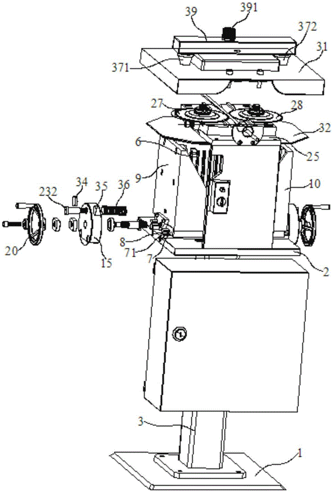
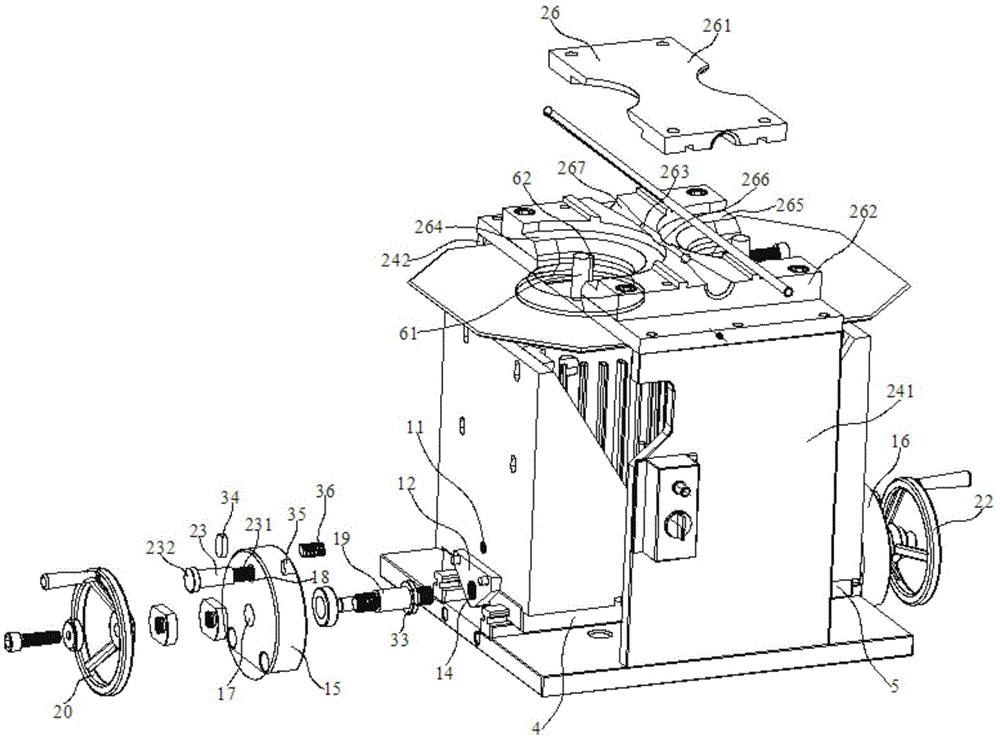
[0028] Embodiment: A stripping device for the metal sheath in cables, comprising: a base 1, a fixed base plate 2, a column 3 fixed between the base 1 and the fixed base plate 2, left and right motor brackets 4, 5 and 2 motors 6; one of the 2 motors 6 is installed on the left motor bracket 4, and the other is installed on the right motor bracket 5, and the respective lower surfaces of the left and right motor brackets 4 and 5 are fixed with 2 motors in parallel. Slider 7, described fixed base plate 2 is provided with 2 line rails 8 in parallel, and described line rail 8 is embedded in the groove 71 of slide block 7 respectively of left and right motor support 4,5 respectively, and described left, right Left and right baffle plates 9, 10 with adjusting screw holes 11 are respectively fixed on the outer sides of motor brackets 4, 5 respectively, and left and right connecting plates with driving screw holes 14 are respectively fixed on the outer sides of the left and right baffle p...


PUM


Abstract

The invention discloses a stripping device for a metal protective layer in a cable. The stripping device for the metal protective layer in the cable comprises a base, a fixing bottom board and two motors. The lower surface of a left motor support and the lower surface of a right motor support are respectively and fixedly provided with two sliding blocks in parallel. The outer side of the left motor support and the outer side of the right motor support are fixedly provided with a left baffle and a right baffle respectively, wherein the left baffle and the right baffle are respectively provided with an adjusting screw hole. The outer side of the left baffle and the outer side of the right baffle are fixedly provided with a left connecting board and a right connecting board respectively, wherein the left connecting board and the right connecting board are respectively provided with a driving screw hole. The left connecting board and the right connecting board are located between two linear rails and the driving screw holes are formed in the portions below the left motor support and the right motor support. Circular grooves are formed in the end face, corresponding to the left baffle, of a left fixing base and in the end face, corresponding to the right baffle, of a right fixing base. Screws of two limiting bolts are sleeved with two springs respectively and the two springs are located between the left fixing base and the left baffle and the right fixing base and the right baffle. A left oil injection groove and a right oil injection groove are formed in a shield and located over a left circular cutting sheet and a right circular cutting sheet respectively. The stripping device for the metal protective layer in the cable solves the problem that the metal protective layer is difficult to cut and strip in the processes of detection, connection and installation of the cable sleeved with metal, the stripping efficiency is improved, and the metal protective layer can be stripped in a large length.

Description

technical field [0001] The invention relates to a cable processing device, in particular to a stripping device for metal sheath in cables. Background technique [0002] In order to meet the requirements of electromagnetic field shielding and anti-mechanical damage in various complex environments, wire and cable are equipped with copper, aluminum, steel and other metal materials or their alloys in the product design and manufacturing process. The metal shielding sheath composed of materials, that is, the cable metal sheath (also known as the metal sheath), the metal sheath is wrapped with various metal strips, longitudinally wrapped, welded into a tubular or thin round wire wrapped and other structures The form is set on the outer layer of the cable core. For cables with such a metal sheath, in the process of manufacture, installation and maintenance, the metal sheath needs to be cut and stripped before the cable core is inspected, spliced ​​and installed. Due to the existe...

Claims


Application Information

Patent Timeline
Patent Type & Authority Patents(China)
IPC IPC(8): H02G1/12H01R43/28
Inventor 余建朝王国权沈建新李宁范建华孙明华曹卫忠刘党荣
Owner JIANGSU HENGTONG WIRE & CABLE TECH
Why Eureka
Try Eureka