Mechanical delay switch

A delay switch, mechanical technology, applied in the field of mechanical processing and manufacturing, can solve the problems of delay switches that are not equipped with software control and cannot manufacture electronic timers, etc., and achieve the effect of simple structure

Inactive Publication Date: 2014-03-26
重庆市合川区何茗机械加工厂
View PDF0 Cites 4 Cited by
  • Summary
  • Abstract
  • Description
  • Claims
  • Application Information

AI Technical Summary

Problems solved by technology

At the same time, for some mechanical processing factories, they are usually not equipped with software control, electronic timer technology related produ...

Method used


Image

  • Mechanical delay switch

Examples


Embodiment Construction

[0015] The technical solution of the present invention will be further described below in conjunction with the accompanying drawings and embodiments.

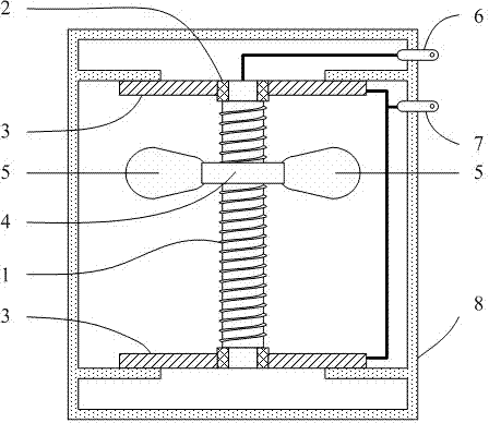
[0016] The invention relates to a mechanical delay switch. One of its specific implementations is as figure 1 shown; in order to facilitate the representation of the internal structure, figure 1 It shows the schematic diagram of the structure of the mechanical delay switch after cutting the insulating shell and the chassis. The mechanical delay switch includes an insulating shell 8, and a delay switch device fixedly arranged in the insulating shell 8. The delay switch device includes a screw 1 and two chassis 3 fixedly installed on both ends of the screw through an insulating member 2. The screw 1 And chassis 3 is copper. The screw 1 is threaded with a nut piece 4, and the nut piece 4 is also made of copper. The outer side of the nut piece 4 is fixedly provided with two counterweights 5 with the same weight evenly distribute...


PUM


Abstract

The invention provides a mechanical delay switch. The mechanical delay switch comprises a screw rod and two base plates which are fixedly installed at the two ends of the screw rod through insulating pieces, and the screw rod and the base plates are made of electric conduction materials. The screw rod is in threaded connection with a nut piece, at least two balance weight pieces with the same weight are fixedly arranged on the outer side of the nut piece, the balance weight pieces are evenly distributed in the horizontal circumference direction, and the nut piece can freely slide downwards in a rotating mode on the screw rod through the gravity of the balance weight pieces. The balance weight pieces and the nut piece are made of electric conduction materials, the balance weight pieces are conducted with the screw rod through the nut piece, and when the nut piece rotates to the end of the screw rod, the balance weight pieces can make contact with the base plates at the ends of the screw rod. One end of the screw rod is electrically connected to a first output electrode. The two base plates are connected in parallel through a wire and then electrically connected to a second output electrode. The mechanical delay switch is simple in structure, all components of the mechanical delay switch can be produced in a machining mode, and the mechanical delay switch is suitable for being produced and manufactured in machining factories.

Description

technical field [0001] The invention relates to the technical field of machining and manufacturing, in particular to a mechanical delay switch. Background technique [0002] Delay switches are widely used in many electromechanical control fields. But at present, most of the delay switches are realized by software control, or more accurate delay control is realized by means of electronic timers, which have the disadvantages of relatively complex structure and high technical requirements. However, in practical industrial applications, it is not necessary to perform very precise delay control in many cases, and only needs to have a delay on-off control function of several seconds to achieve simple delay control. At the same time, for some mechanical processing factories, they are usually not equipped with relevant production equipment and technical personnel for software control and electronic timer technology, so they cannot manufacture and produce delay switches with softwar...

Claims


Application Information

Patent Timeline
IPC IPC(8): H01H7/08
Inventor 邓方兰
Owner 重庆市合川区何茗机械加工厂
Why Eureka
Try Eureka