
Rectifying and amplitude limiting circuit with multiple time constants and passive radio frequency tag

A time constant and limiting circuit technology, applied in the field of radio frequency identification, can solve the problems of communication failure and saturation of the receiving end of the card reader, and achieve the effect of improving the reading and writing distance, improving the demodulation ability and fast control.

Active Publication Date: 2014-03-26
EXCELIO TECH SHENZHEN
View PDF4 Cites 13 Cited by
  • Summary
  • Abstract
  • Description
  • Claims
  • Application Information

AI Technical Summary

Problems solved by technology

When the passive RFID tag is too close to the card reader or the electromagnetic energy sent by the card reader is too strong, the load modulation signal coupled back from the RFID tag end will easily cause saturation at the receiving end of the card reader, resulting in communication failure
This kind of failure is more likely to occur in the RTF communication mode (Reader Talk First) where the reader first sends a command and then waits for the RFID tag to respond.

Method used


Image

  • Rectifying and amplitude limiting circuit with multiple time constants and passive radio frequency tag
  • Rectifying and amplitude limiting circuit with multiple time constants and passive radio frequency tag
  • Rectifying and amplitude limiting circuit with multiple time constants and passive radio frequency tag

Examples


Embodiment Construction

[0033] The following will clearly and completely describe the technical solutions in the embodiments of the present invention with reference to the accompanying drawings in the embodiments of the present invention. Obviously, the described embodiments are only some, not all, embodiments of the present invention. Based on the embodiments of the present invention, all other embodiments obtained by persons of ordinary skill in the art without creative efforts fall within the protection scope of the present invention.

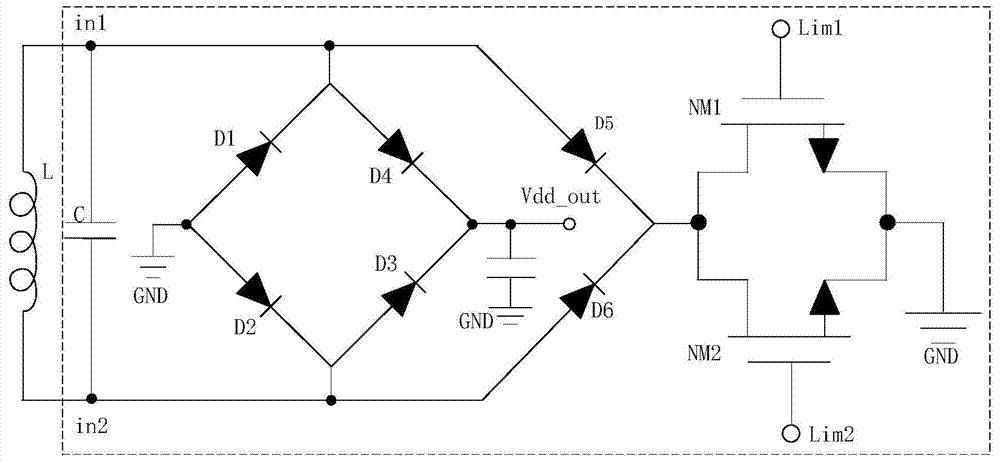
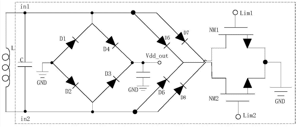
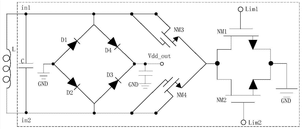
[0034] figure 1 It is a structural diagram of the first embodiment of the circuit overall structure of the present invention. A rectifying and limiting circuit with multiple time constants described in the present invention includes:

[0035] A resonant capacitor C, which is connected in parallel with the resonant inductance L between the first antenna terminal in1 and the second antenna terminal in2, is used to form a resonant circuit with the resonant inductance ...


PUM


Abstract

The invention belongs to the technical field of radio frequency identification, and particularly relates to a rectifying and amplitude limiting circuit with multiple time constants, and a passive radio frequency tag containing the rectifying and amplitude limiting circuit. By applying different time constants on the control ends of two discharging paths of the rectifying and amplitude limiting circuit, namely that the analog control signals with adjusted voltage amplitude can be carried out at different switching speeds, so the switching between complete opening and complete closing of the two discharging paths is realized; the applicable discharging is carried out according to the size of charge amount at the antenna end and the energy level of the tag, so the demodulation level of the tag is improved, and the reading and writing distance of the tag is improved.

Description

technical field [0001] The invention belongs to the technical field of radio frequency identification, and specifically refers to a rectifying and limiting circuit with multiple time constants and a passive radio frequency tag including the rectifying and limiting circuit. Background technique [0002] The passive radio frequency identification (Radio Frequency Identification, RFID) tag does not have a battery itself, and it works by the electromagnetic energy sent by the card reader. Because of its simple structure, economical and practical, it has been widely used in logistics management, asset tracking and mobile medical fields. [0003] When a passive RFID tag works, it absorbs the electromagnetic energy sent by the reader from the surrounding environment. After the passive RFID tag absorbs energy, it rectifies a part of the energy into a DC power supply for the internal circuit of the passive RFID tag; the passive RFID tag also inputs another part of the energy into th...

Claims


Application Information

Patent Timeline
Patent Type & Authority Applications(China)
IPC IPC(8): G06K19/077
CPCG06K19/0723H02M7/062G06K19/0715H02J50/12H02M7/043H02M1/322
Inventor 吴边韩富强漆射虎
Owner EXCELIO TECH SHENZHEN
Learn More