
Hinge pin tensile test device

A technology of tension testing and pin shaft, which is applied to measuring devices, force/torque/power measuring instruments, instruments, etc., can solve time-consuming and labor-intensive problems, and achieve the effect of time-consuming, labor-intensive, effective and stable force application

Inactive Publication Date: 2014-03-26
STATE GRID CORP OF CHINA +1
View PDF7 Cites 2 Cited by
  • Summary
  • Abstract
  • Description
  • Claims
  • Application Information

AI Technical Summary

Problems solved by technology

[0003] The present invention aims to provide a pin tension testing device to solve the time-consuming and labor-intensive technical problems in the pin tension testing process in the prior art

Method used


Image

  • Hinge pin tensile test device

Examples


Embodiment Construction

[0016] Hereinafter, the present invention will be described in detail with reference to the drawings and examples. It should be noted that, in the case of no conflict, the embodiments in the present application and the features in the embodiments can be combined with each other.

[0017] The pin shaft to be tested is the locking pin of the suspension insulator.

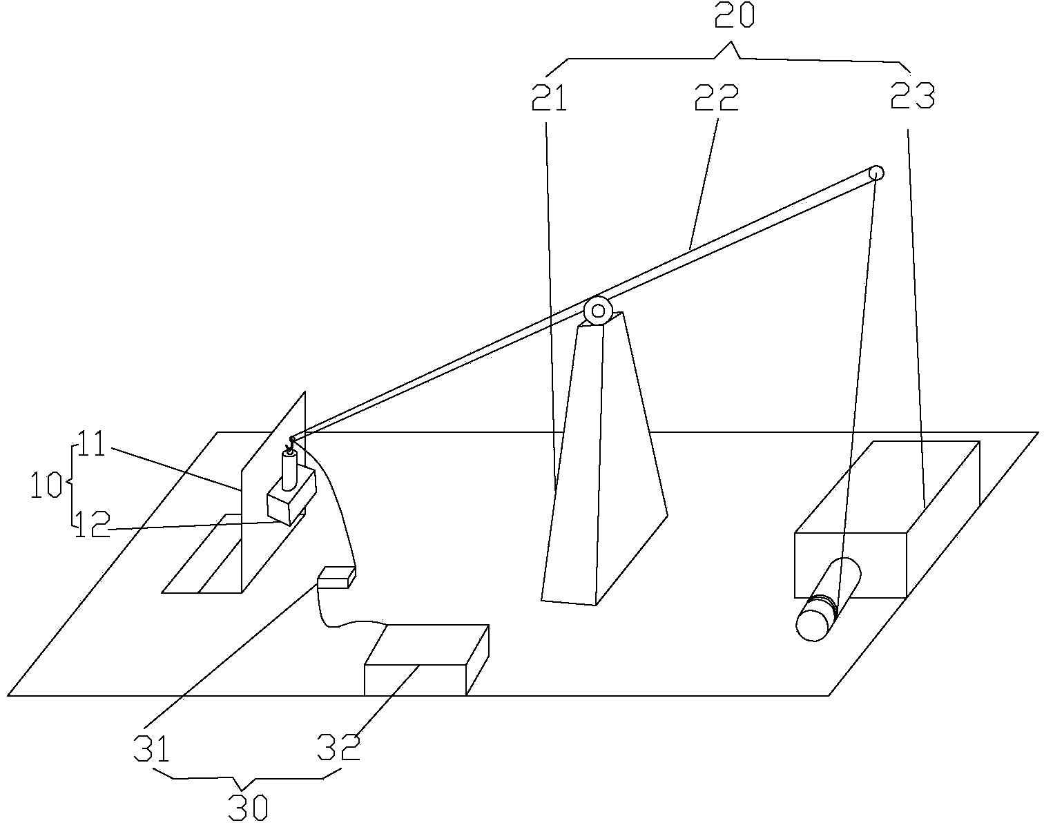
[0018] Such as figure 1 As shown, according to the embodiment of the present invention, the pin shaft tensile testing device includes a fixing part 10 , a force applying part 20 and a data collection and processing part 30 . The fixed part 10 is fixedly arranged on the tension test workbench, and the pin shaft to be tested is installed on the fixed part 10; the force application part 20 is arranged on the tension test workbench, and the force application end of the force force part 20 is connected to the pin shaft to be tested; data acquisition The processing unit 30 is connected to the force applying unit 20 and di...


PUM


Abstract

The invention provides a hinge pin tensile test device. The hinge pin tensile test device comprises a fixing part (10), a force applying part (20) and a data collecting and processing part (30), wherein the fixing part (10) is used for mounting a hinge pin to be tested and is fixedly arranged on a tensile test workbench, the force applying part (20) is arranged on the tensile test workbench, the force applying end of the force applying part (20) is connected to the hinge pin to be tested, and the data collecting and processing part (30) is connected with the force applying part (20) and is used for detecting and displaying a tensile test result. The hinge pin tensile test device solves the technical problem that time and labor are consumed in the tensile testing process of the hinge pin in the prior art.

Description

technical field [0001] The invention relates to the field of mechanical tensile tests, in particular to a pin shaft tensile test device. Background technique [0002] At present, the locking pin tension detection device used by suspension insulator manufacturers and suspension insulator testing institutions is to process the steel cap of the suspension insulator into a mold for fixing the locking pin, and then install the locking pin of the suspension insulator tightly. Fixed on the steel cap mould. Using the principle of leverage, the tester exerts force on the locking pin manually. Before carrying out the tensile test, the tester manually adjusted the position of the steel cap mold to ensure that the locking pin hole of the fixing locking pin device was on the same vertical axis as the force application direction. In the past, the detection process was all manual, relying on manpower to put in and take out the locking pin, and relying on the naked eye and feeling to adju...

Claims


Application Information

Patent Timeline
Patent Type & Authority Applications(China)
IPC IPC(8): G01L5/00
Inventor 钱文晓张国力刘会斌孟杰王延伟石海鹏陈忠源张阳
Owner STATE GRID CORP OF CHINA
Learn More