
Protective casing lifting equipment

A casing and equipment technology, applied in construction, sheet pile walls, foundation structure engineering, etc., can solve the problems of low work efficiency, high risk factor, backward control mode, etc., achieve simple manual operation, high degree of automation, and improve the overall The effect of the process

Inactive Publication Date: 2014-03-26
BEIJING SANY HEAVY MASCH CO LTD
View PDF6 Cites 3 Cited by
  • Summary
  • Abstract
  • Description
  • Claims
  • Application Information

AI Technical Summary

Problems solved by technology

[0004] 1. The layout of the hydraulic cylinder and the clamping mechanism is unreasonable. The clamping force obtained by holding the cylinder tightly depends on the pulling force of the cylinder. Not only is the clamping force small, but this layout is also a waste of the maximum force that the cylinder can provide. Make the best use of the oil cylinder;
[0005] 2. The pulling diameter is not variable, the application range is small, and the casing with larger diameter cannot be pulled effectively;
[0006] 3. Most of the control methods are manual control, the control method is backward, the work efficiency is low, and the operation is complicated and cumbersome; the distance between the operator and the equipment is relatively short, and the risk factor is high

Method used


Image

  • Protective casing lifting equipment
  • Protective casing lifting equipment
  • Protective casing lifting equipment

Examples


Embodiment Construction

[0032] It should be noted that, in the case of no conflict, the embodiments of the present invention and the features in the embodiments can be combined with each other. The present invention will be described in detail below with reference to the accompanying drawings and examples.

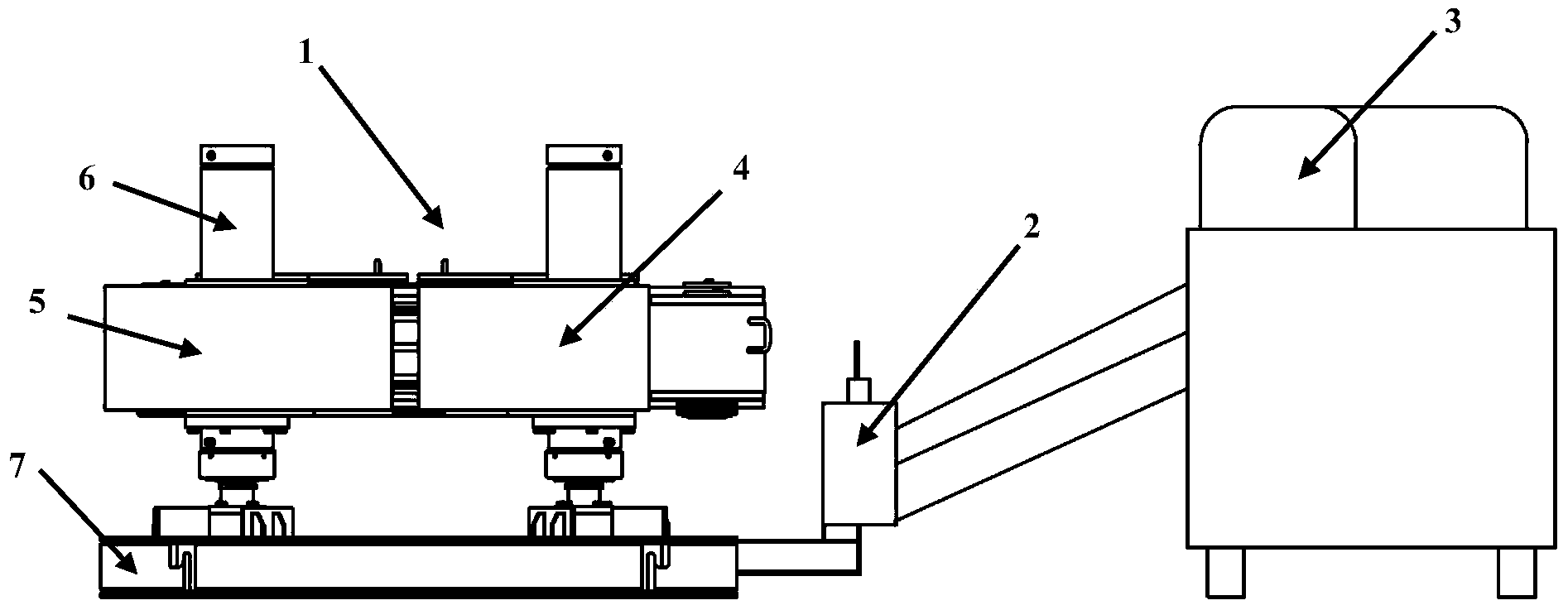
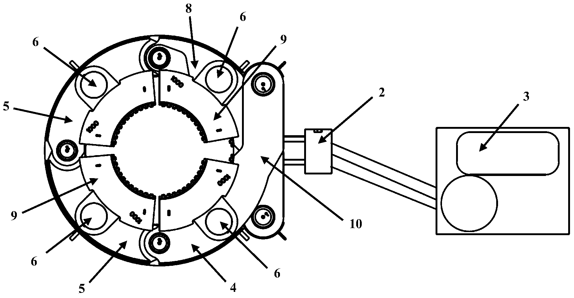
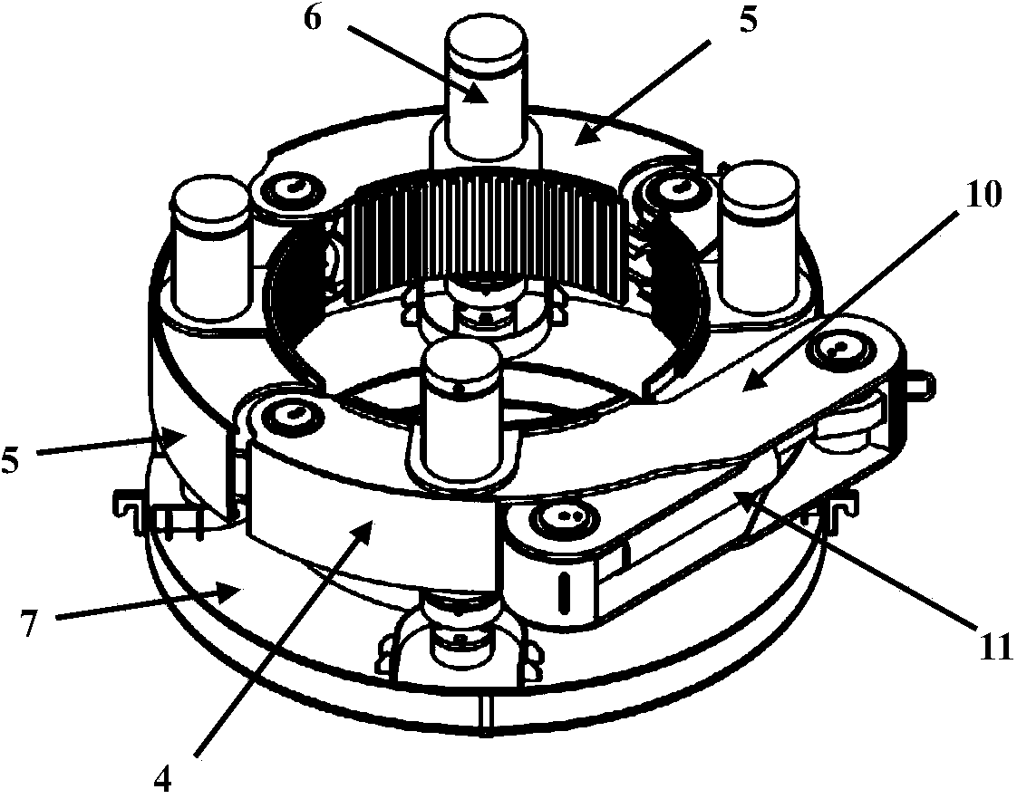
[0033] Figure 1 to Figure 4 It is the related drawings of this embodiment. As shown in the figure, the casing lifting device described in this embodiment includes a clamping assembly 1 for pulling out the casing, and a clamping assembly 1 for controlling the clamping assembly. The remote control assembly 2 of 1 and the power assembly 3 that provides power.

[0034] Wherein, the clamping assembly 1 comprises a head clamping block 4, a tail end clamping block 8 and two middle clamping blocks 5, the head end clamping block 4, the middle clamping block 5, and the tail end clamping block 8 are all It is an arc-shaped block structure and is provided with vertical lifting cylinders 6 respectively, an...


PUM


Abstract

The invention provides protective casing lifting equipment which comprises a clamping assembly, a remote control assembly and a power assembly for providing power. The clamping assembly comprises a head end clamping block, a tail end clamping block and at least one middle clamping block, the head end clamping block, the middle clamping block and the tail end clamping block are of arc block-shaped structures and are respectively provided with a vertical lifting oil cylinder, and the head end clamping block, the middle clamping block and the tail end clamping block are sequentially hinged to form a cylinder-shaped structure. The head end clamping block and the tail end clamping block are respectively provided with an enclasping arm, the enclasping arms extend towards the outsides of each other and are staggered, and a horizontally-arranged enclasping oil cylinder is hinged between the two enclasping arms. The protective casing lifting equipment can effectively liberate a rotary drilling rig from the construction link of lifting a protective casing, and greatly accelerate the overall process of construction projects. In addition, the enclasping arms are staggered and arranged in a scissor shape, the maximum jacking force of the enclasping oil cylinder can be fully converted into enclasping force of the clamping assembly, and the enclasping oil cylinder can play the greatest role.

Description

technical field [0001] The invention relates to the field of engineering machinery, in particular to a casing lifting device. Background technique [0002] With the rapid development of rotary drilling rigs in my country's piling industry, full casing construction, a new safe and environmentally friendly piling method, has also been vigorously developed. Therefore, the construction equipment matched with the full casing construction has also been rapidly popularized and applied. At present, among the complete casing construction equipment, the equipment for lowering and pulling out the casing by the rotary drilling rig mainly includes the rotary drilling driving fountain, the rotary drilling pipe rubbing machine, and the rotary drilling rig. Among these types of equipment, the rotary drilling rig is complex and expensive (tens of millions); the driving fountain and the tube rubbing machine generally require the cooperation of a rotary drilling rig to construct, that is to s...

Claims


Application Information

Patent Timeline
IPC IPC(8): E02D9/02
Inventor 冯建伟
Owner BEIJING SANY HEAVY MASCH CO LTD
Learn More