Clamp for hydraulic pipe expansion and fin distributing method of clamp

A practical and fixture technology, which is applied in the field of hydraulic expansion tubes, can solve the problems of uneven wall thickness, low yield, and not tight riveting of aluminum tubes and fins, etc., and achieves the effect of convenient use and simple structure

Inactive Publication Date: 2014-03-26
CHANGZHOU QUNXING REFRIGERATION EQUIP
View PDF6 Cites 5 Cited by
  • Summary
  • Abstract
  • Description
  • Claims
  • Application Information

AI Technical Summary

Problems solved by technology

[0003] In the process of hydraulic tube expansion, because the inside of the aluminum tube is in direct contact with the inner wall of the aluminum tube, the force is uniform, and the expansion of the tube under the action of the liquid will not cause various defects caused by the above-mentioned mechanical tube expansion. The tooth shape inside the aluminum tube is not Damage and deformation occur, but the yield is low
There will always be local unevenness and errors in the wall thickness, so in the process of hydraulic tube expansion, the aluminum tube will burst (up to 40%) when the constant pressure is not fully reached. If the set constant pressure is not reached, there will be Defects such as local incomplete riveting of aluminum tubes and fins

Method used


Image

  • Clamp for hydraulic pipe expansion and fin distributing method of clamp
  • Clamp for hydraulic pipe expansion and fin distributing method of clamp
  • Clamp for hydraulic pipe expansion and fin distributing method of clamp

Examples


Embodiment 1

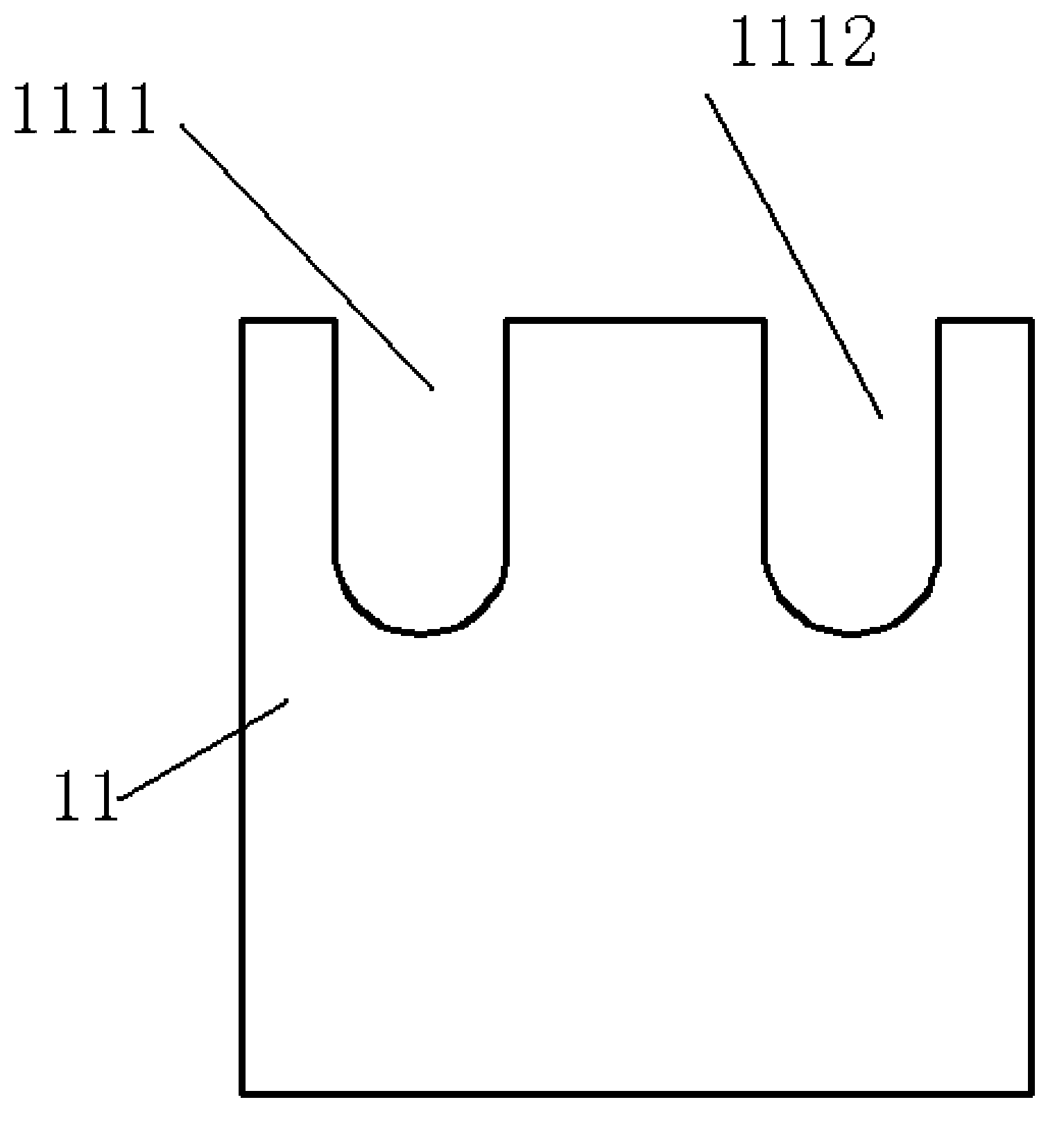
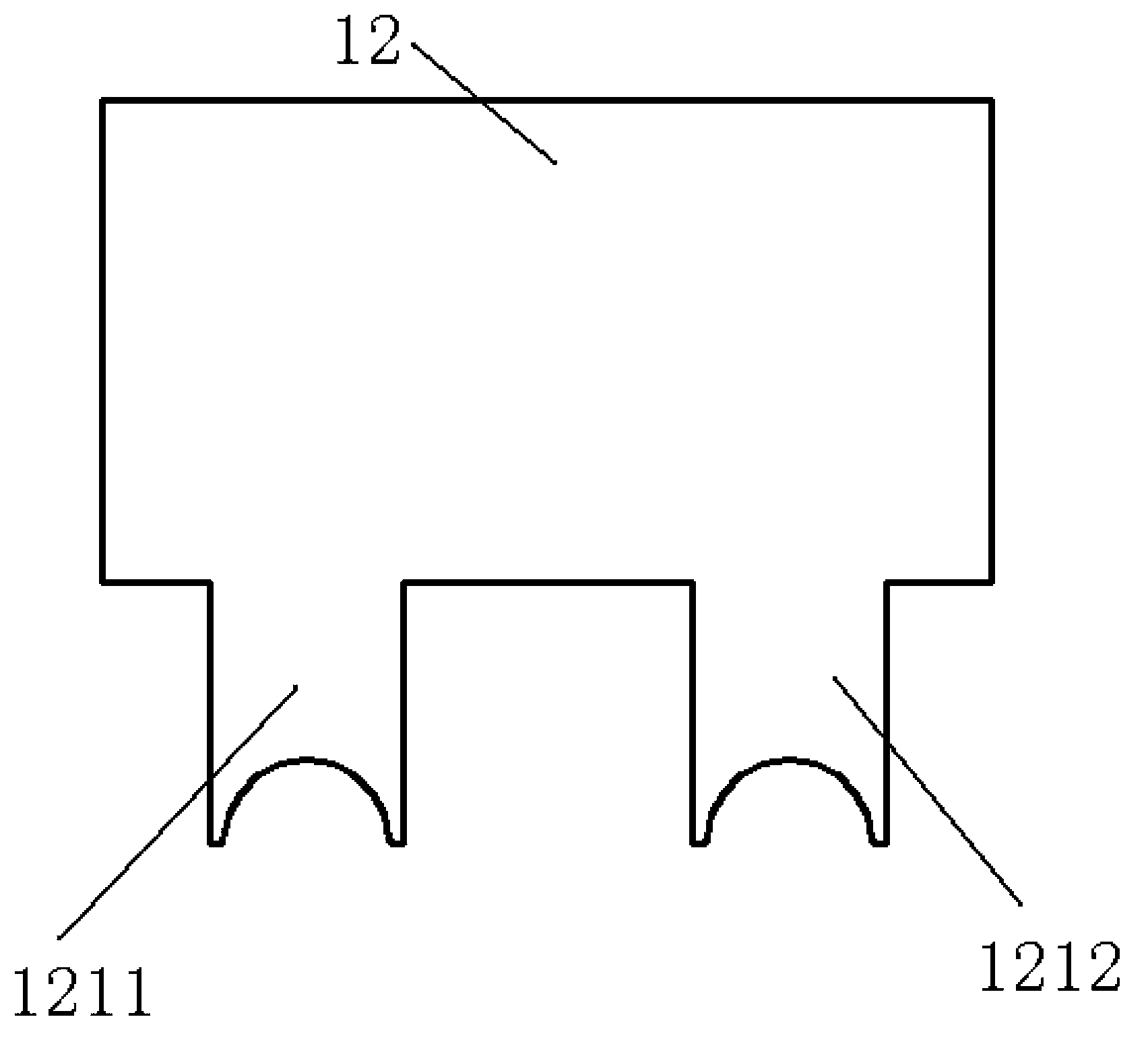
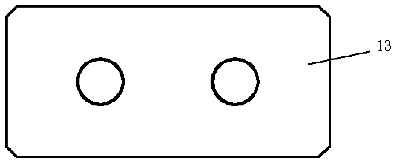
[0033] refer to Figure 1-5 As shown, the clamp for hydraulic pipe expansion includes a lower die 11 and an upper die 12 . Wherein the lower die 11 is provided with at least one "U"-shaped groove, and in this embodiment, two "U"-shaped grooves are selected, that is, the first groove 1111 and the second groove 1112, the first groove 1111 and the second groove. The two grooves 1112 have the same shape and are located on the same level. The distance between the first groove 1111 and the second groove 1112 matches the two holes 131 for inserting aluminum tubes in the fin. The first groove 1111 and the bottom of the second groove 1112 are both arc-shaped; the lower mold 11 is also provided with a plurality of slots 112 for discharging fins, wherein the slots 112 run through the side wall of the groove. The upper mold 12 is provided with at least one protrusion 121. In this embodiment, two protrusions matching the first groove 1111 and the second groove 1112 are selected, that is, ...

Embodiment 2

[0040] refer to Figure 6-7 As shown, the clamp for hydraulic expansion includes a lower die 21 and an upper die 22 . The lower die 21 is provided with at least one "U"-shaped groove 211. In this embodiment, one "U"-shaped groove 211 is selected. The bottoms of the grooves 211 are all arc-shaped. The diameters of the aluminum tubes are the same; the lower mold 21 is also provided with a plurality of slots 212 for fin discharge, wherein the slots 212 run through the side walls of the grooves 211 . The upper mold 22 is provided with at least one protrusion 221. In this embodiment, one protrusion 221 matching the above-mentioned groove 211 is selected. An approximate circle is formed, and the diameter of the approximate circle is the same as that of the expanded aluminum tube, which is used to protect the aluminum tube from expanding within a fixed range, so as not to cause rupture due to involuntary expansion.

[0041] Refer to Example 1 for the sheet arranging method using th...


PUM


Abstract

The invention provides a clamp for hydraulic pipe expansion and a fin distributing method of the clamp. The clamp comprises a lower mold and an upper mold. The lower mold is provided with at least one groove, the bottom of the groove is arc, and the groove is in a U shape. The lower mold is provided with a plurality of fin distributing grooves used for the fins to be placed, and the fin distributing grooves penetrate through the side wall of the groove. At least one protrusion is arranged on the upper mold, the top of the protrusion is arc and matched with the groove in shape. The clamp is simple in structure and convenient to use, the clamp is used for hydraulic pipe expansion, due to the fact that pipe expansion is limited within a set range, partial unevenness, thinning, deformation, crack and damage can not happen, and the yield reaches 98%.

Description

technical field [0001] The invention relates to the technical field of hydraulic pipe expansion, in particular to a clamp for hydraulic pipe expansion and a method for arranging sheets thereof. Background technique [0002] At present, the aluminum tubes of frost-free aluminum tubes and aluminum fin evaporators for refrigerators are mainly flat tubes (smooth tubes inside), and the processing of internal tooth aluminum tubes (trapezoidal teeth and high and low teeth) required by foreign companies is still a domestic one. blank. As we all know, the refrigerant directly exchanges heat with the inner surface of the aluminum tube, and the size of the inner surface of the aluminum tube directly determines the heat exchange performance. In order to improve the heat exchange performance and reduce power consumption, the refrigeration industry has made great efforts to study how to increase the inner surface. Therefore, the high-performance internal tooth aluminum tubes mentioned ab...

Claims


Application Information

Patent Timeline
Patent Type & Authority Applications(China)
IPC IPC(8): B21D26/047B21D53/08
Inventor 蒋文军
Owner CHANGZHOU QUNXING REFRIGERATION EQUIP
Why Eureka
Try Eureka