A position calibration device and calibration method for a light tube light bar

A technology for calibrating devices and light bars, applied in position/direction control, mechanical control devices, devices for preventing/limiting/recovering the movement of parts of the control mechanism, etc. and other problems, to achieve the effect of convenient fabrication, simple operation and simple method

Inactive Publication Date: 2017-01-04
SUZHOU BAIAOLI OPTOELECTRONICS TECH
View PDF9 Cites 0 Cited by
  • Summary
  • Abstract
  • Description
  • Claims
  • Application Information

AI Technical Summary

Problems solved by technology

[0005] In order to overcome the deficiencies in the above-mentioned prior art, the present invention provides a position calibration device for lamp tubes and light strips. By placing the lamp tubes equipped with light bars on the calibration device, the sliding parts and fixing parts are used. Synergistic combination realizes the precise adjustment and calibration of the position of the light bar in the lamp tube, so as to avoid the occurrence of bad phenomena such as improper plugging or electric leakage during the assembly of the whole lamp, and at the same time avoid the harm caused by the rupture of the lamp tube to the operator

Method used


Image

  • A position calibration device and calibration method for a light tube light bar
  • A position calibration device and calibration method for a light tube light bar

Examples


Embodiment Construction

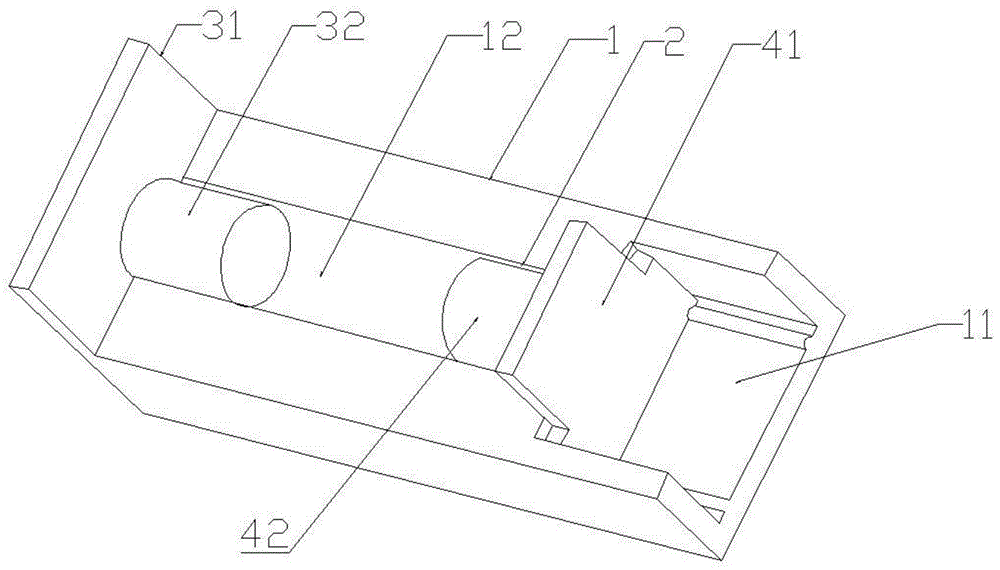
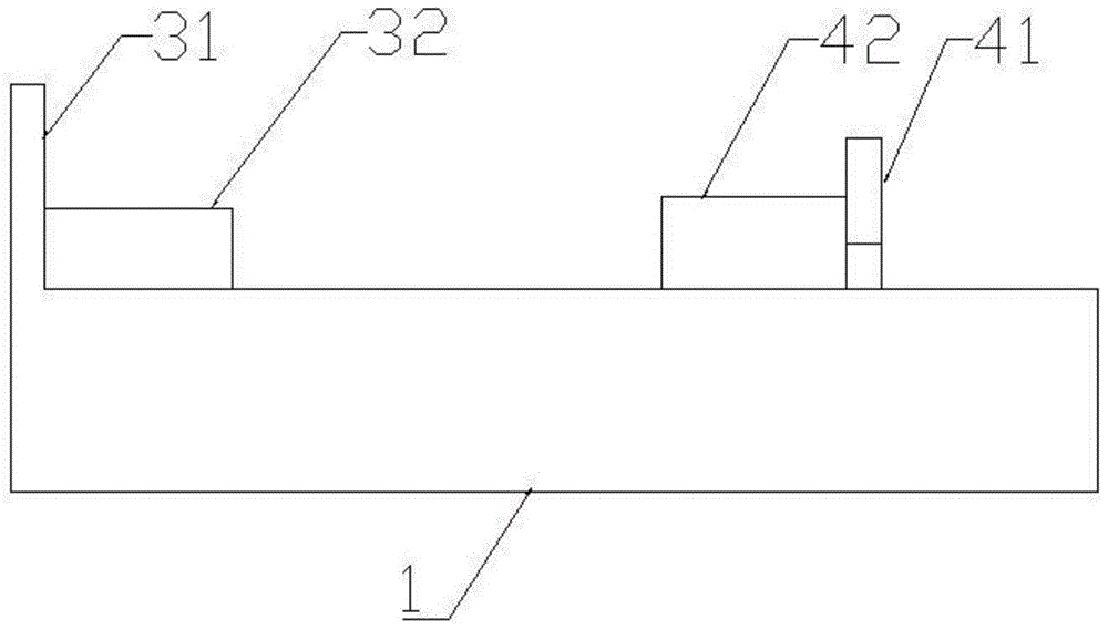
[0028] The present invention will be described in further detail below in conjunction with the accompanying drawings. It should be noted that the accompanying drawings are only used to explain the present invention, which is a schematic description of the embodiments of the present invention, and should not be construed as a limitation of the present invention.

[0029] In the description of the present invention, unless otherwise specified and limited, the terms "installation", "connection" and "connection" should be understood in a broad sense, for example, it can be a fixed connection, a detachable connection, or an integrated Connection; it can be a mechanical connection or an electrical connection; it can be a direct connection or an indirect connection through an intermediary, and it can be the internal communication of two components. Those of ordinary skill in the art can understand the specific meanings of the above terms in the present invention in specific situations...


PUM


Abstract

The invention discloses a device for calibrating the position of a lamp bar in a lamp tube. The device comprises a device body on which a chute and a groove used for placing a lamp tube are disposed, a fixed member disposed on one end of the device body, and a sliding member disposed on the other end of the device body and capable of moving in the chute. The fixed member and the sliding member are both equipped with protruding blocks passing through the lamp tube. When the sliding member moves on the device body, the protruding blocks may calibrate the position of a lamp bar in the lamp tube. By placing the lamp tube equipped with the lamp bar on the device and using the cooperation of the sliding member and the fixed member, accurate position adjustment and calibration of the lamp bar in the lamp tube is achieved. Therefore, unhealthy phenomena of out of place of an end cap or electric leakage are prevented when a lamp is assembled and harm to operators caused by lamp tube rupture is simultaneous prevented. Additionally, the invention also provides a method for calibrating the position of a lamp bar in a lamp tube using the above device.

Description

technical field [0001] The invention relates to the technical field of lamp tube and light bar installation, in particular to a position calibration device and calibration method for a light tube and light bar. Background technique [0002] Light strips (that is, light strips) commonly include LED light strips, LED soft light strips, light strips, FPC light strips, etc. LED light bar is a kind of light tube light bar, which can assemble LEDs on a strip-shaped FPC (flexible circuit board) or PCB hard board to form a flexible LED light bar or a rigid LED light bar. Flexible LED light strips generally use FPC as the assembly circuit board, and use SMD high-brightness LEDs as the light source. Every 3 lights are a unit, and every 50 cm is a large length unit. The thickness of this product is only It is as thick as a coin and does not take up space. Moreover, the flexible LED light strip can be cut at will or extended without affecting the light emission. The reason is that the ...

Claims


Application Information

Patent Timeline
Patent Type & Authority Patents(China)
IPC IPC(8): G05D3/00G05G5/00
Inventor 赵兴唐金龙陆利兵
Owner SUZHOU BAIAOLI OPTOELECTRONICS TECH
Why Eureka
Try Eureka