
Debris flow siltation and overflow scope boundary defining method and danger zoning method

A debris flow and range technology, which is used in the boundary delineation of debris flow deposition and flooding, the dangerous zoning of debris flow deposition and flooding areas, and the research field of debris flow deposition fans. question

Active Publication Date: 2014-03-19
CHENGDU UNIVERSITY OF TECHNOLOGY
View PDF4 Cites 10 Cited by
  • Summary
  • Abstract
  • Description
  • Claims
  • Application Information

AI Technical Summary

Problems solved by technology

The technical defects of these methods are mainly reflected in three aspects: First, the debris flow deposition range determined by the maximum outflow distance and maximum outflow width of the debris flow through mathematical statistical methods cannot simultaneously reflect the mud depth, flow depth and flow velocity that characterize the degree of danger of the debris flow The distribution of such parameters in the siltation area cannot further carry out detailed risk zoning of the debris flow siltation area, and this method needs to be based on a large number of historical observation records. Different research areas often need to fit different function equations to study the corresponding debris flow The scope of application of the method is limited; the second is that the numerical simulation method needs to input more model parameters, and the equation solving and simulation process is relatively complicated; As a research basis, the application of the method is limited in areas lacking large-scale topographic maps

Method used


Image

  • Debris flow siltation and overflow scope boundary defining method and danger zoning method
  • Debris flow siltation and overflow scope boundary defining method and danger zoning method
  • Debris flow siltation and overflow scope boundary defining method and danger zoning method

Examples


Embodiment 1

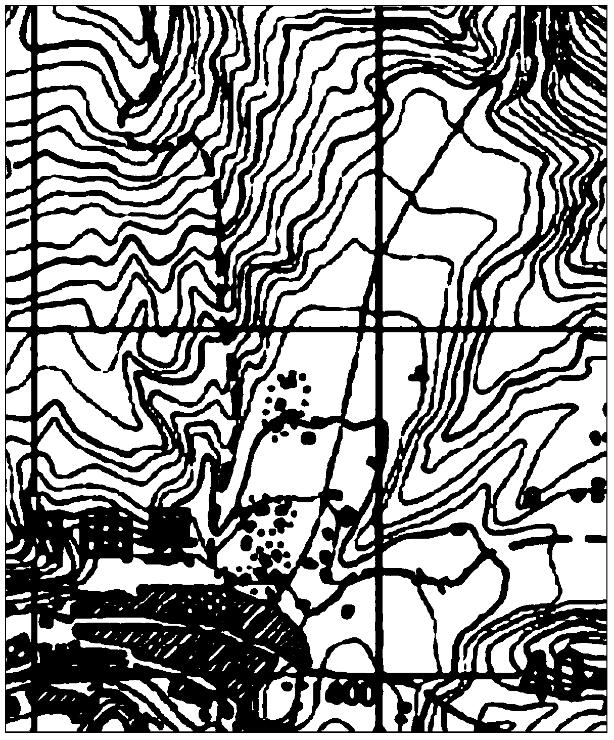
[0076] From the evening of August 7 to the early morning of August 8, 2010, heavy rainfall caused large-scale debris flows to occur simultaneously in Sanyanyugou and Luojiayugou in the north of Zhouqu County, Gansu Province. 4 m 3 and 35.7×10 4 m 3 , causing extremely serious loss of life and property. Using the 1:50000 topographic map of Zhouqu County ( figure 1 ), to delineate the boundary of the debris flow siltation flooding area.

[0077] Step S1, determine the basic data

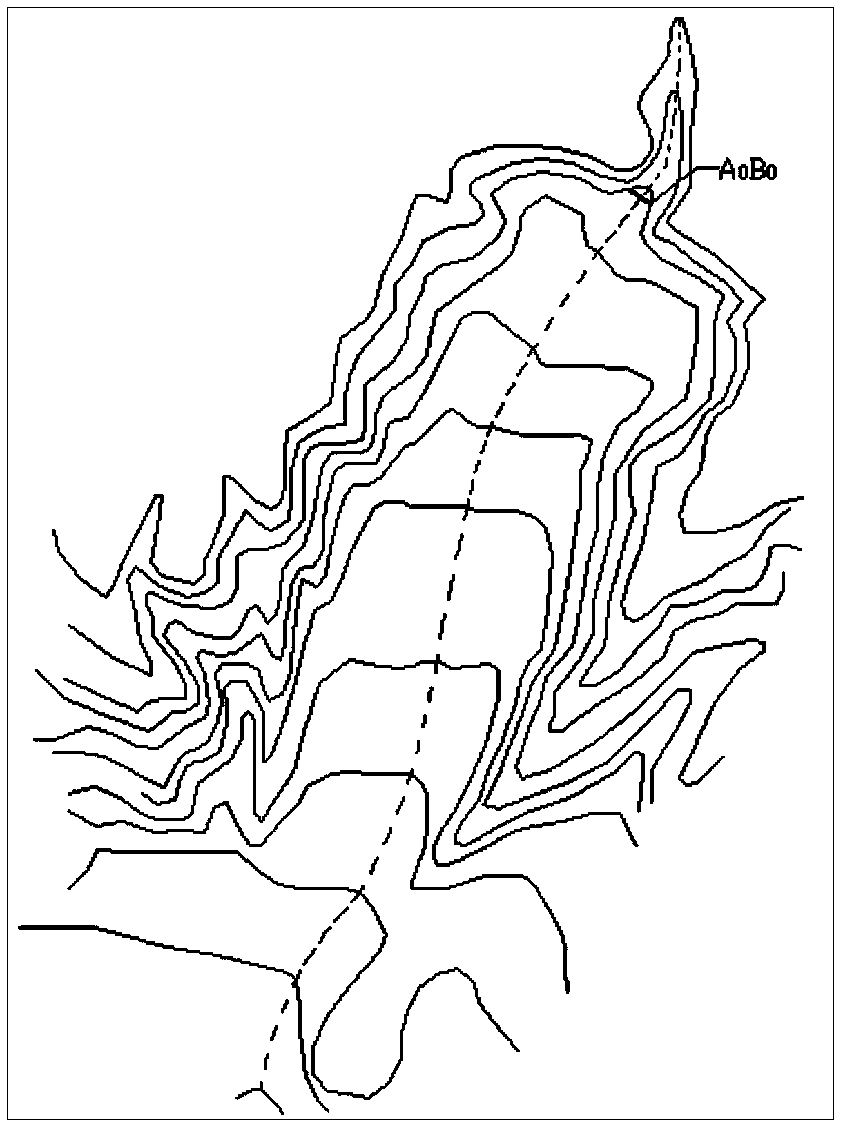
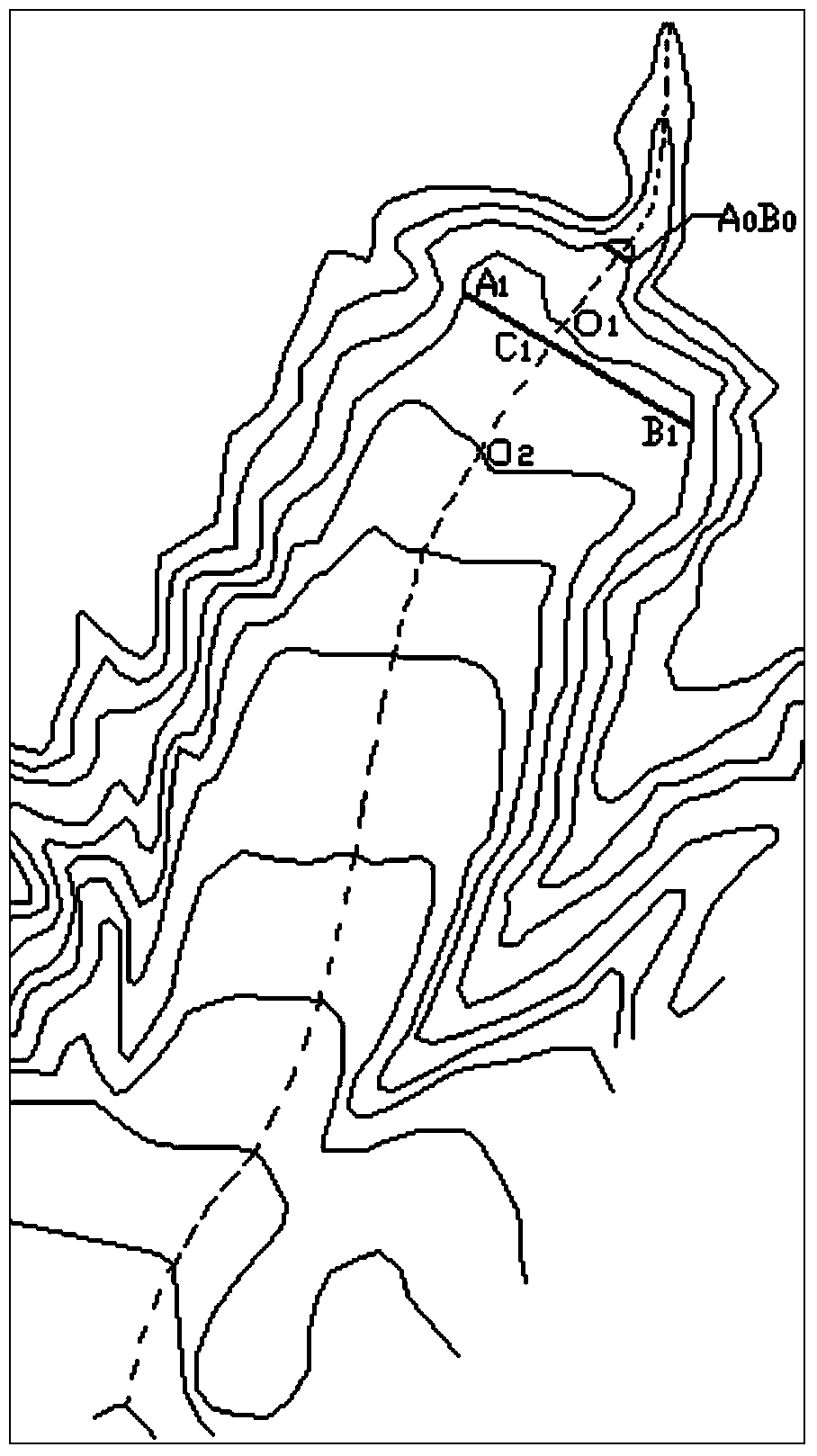
[0078] According to the topographic map of 1:50000, combined with the field investigation, the basic geographical terrain data of the main channel of the debris flow are determined, including: determining the geographical location of the main channel of the debris flow ( figure 2 center dotted line), determine the flow section A of the debris flow ditch mouth 0 B 0 Location( figure 2 ), the measurement determines the cross-section A 0 B 0 Width L 0 =43.65m, determine section A 0 B 0 The ...

Embodiment 2

[0090] Based on the first embodiment, the danger zone of the debris flow accumulation fan is further carried out.

[0091] Step S5, determine the specified cross-section E j f j

[0092] In the "8.7" Sanyanyu debris flow sedimentation and flooding area (elevation range: 1500m ~ 1320m) delineated in the first embodiment, the designated flow section E is determined at intervals of 5m height difference j f j , j = 1, 2...m positions, a total of 36 specified flow sections are determined ( Figure 6 ).

[0093] Measure each section E j f j the width L j ,j=1,2...m, measure and calculate each section E j f j Debris flow hydraulic gradient i j ,j=1,2...m.

[0094] Step S6, determine the specified cross-section E j f j average flow depth h j with the average velocity v j

[0095] Set parameter Q=1712m 3 / s, section E j f j the width L j ,j=1,2...m and the calculated value i of the debris flow hydraulic gradient at each section j Substitute into Equation 5~Equation...


PUM


Abstract

The invention discloses a debris flow siltation and overflow scope boundary defining method and a danger zoning method, and aiming at the defect that a danger range division method for a conventional accumulation fan area needs to take a great amount of observation data in a prior period or a large-scale topographic map as the basis and then application is limited, the invention provides a danger zoning method for a debris flow accumulation fan. According to the method, average flow depth of gully peak flow is taken as a special index to determine that the maximum average flow depth on a main gutter channel of the accumulation fan area is accorded with an assigned overflow cross section position of the special index, and the distribution change and topographical change characteristics of the geographical position of the assigned overflow cross section are used to determine the siltation and overflow scope boundary of the debris flow. The invention further provides a danger zoning method of a siltation and overflow area, which is implemented based on two parameters and syntagmatic relations of the two parameters including the average flow depth and the mean velocity of the debris flow of the assigned overflow cross section. According to the methods, principles are reliable; a computational process is scientific, simple and convenient; the large-scale topographic map and a great amount of historical observation data are not required to be taken as the basis; and the practical application and popularization value is high.

Description

technical field [0001] The invention relates to a method for researching a debris flow accumulation fan, in particular to a method for delineating the boundary of a debris flow silting and flooding area and a method for zoning a debris flow silting and flooding area danger zone. It belongs to the field of debris flow disaster prevention and control and the field of water conservancy engineering. Background technique [0002] Debris flow accumulation fan is the product of debris flow activities, which refers to a fan-shaped area formed by one or more debris flows flooding and depositing at the mouth of a debris flow. The debris flow accumulation fan area at the mouth of the debris flow ditch is often used by people because of its relatively open terrain. However, the debris flow accumulation fan area is also the main place where debris flow disasters occur, and the land use in this area is threatened by potential debris flow disasters. The research on the danger range of de...

Claims


Application Information

Patent Timeline
IPC IPC(8): E02B1/02E02B3/02
Inventor 刘清华唐川余斌朱静黄勋常鸣周伟
Owner CHENGDU UNIVERSITY OF TECHNOLOGY
Learn More