Safety protection device for preventing from mistakenly stepping on accelerator of car
A safety protection device and the technology of mistakenly stepping on the accelerator, which are applied in the direction of the safety device, signal device, and automatic start device of the power plant control mechanism, etc., can solve the problems of unsecured reliability, high cost, poor reliability, etc., and achieve increased safety , Renovation cost is low, the effect of remodeling is easy
- Summary
- Abstract
- Description
- Claims
- Application Information
AI Technical Summary
Problems solved by technology
Method used
Image
Examples
Embodiment 1
[0030] Such as figure 1 As shown, the brake pedal 1 is located on the left side of the accelerator pedal 2, and a brake linkage plate 7 is arranged on the right side of the brake pedal 1. The brake linkage plate 7 is in a "Z" shape with a high left end and a low right end. The top surface fits with the bottom surface of the brake pedal 1 and is fixed by vertical bolts. The holes for the vertical bolts to pass through on the brake linkage plate 7 are elongated holes extending horizontally. By changing the position of the vertical bolt in the elongated hole, the lateral position of the brake linkage plate 7 can be changed.
[0031] Such as figure 1 As shown, an accelerator linkage plate 3 is provided on the left side of the accelerator pedal 2. The accelerator linkage plate 3 is in the shape of a “Z” with a high left end and a low right end. The right end of the accelerator linkage plate 3 is connected to the accelerator pedal 2 through horizontal bolts, and the accelerator lin...
Embodiment 2
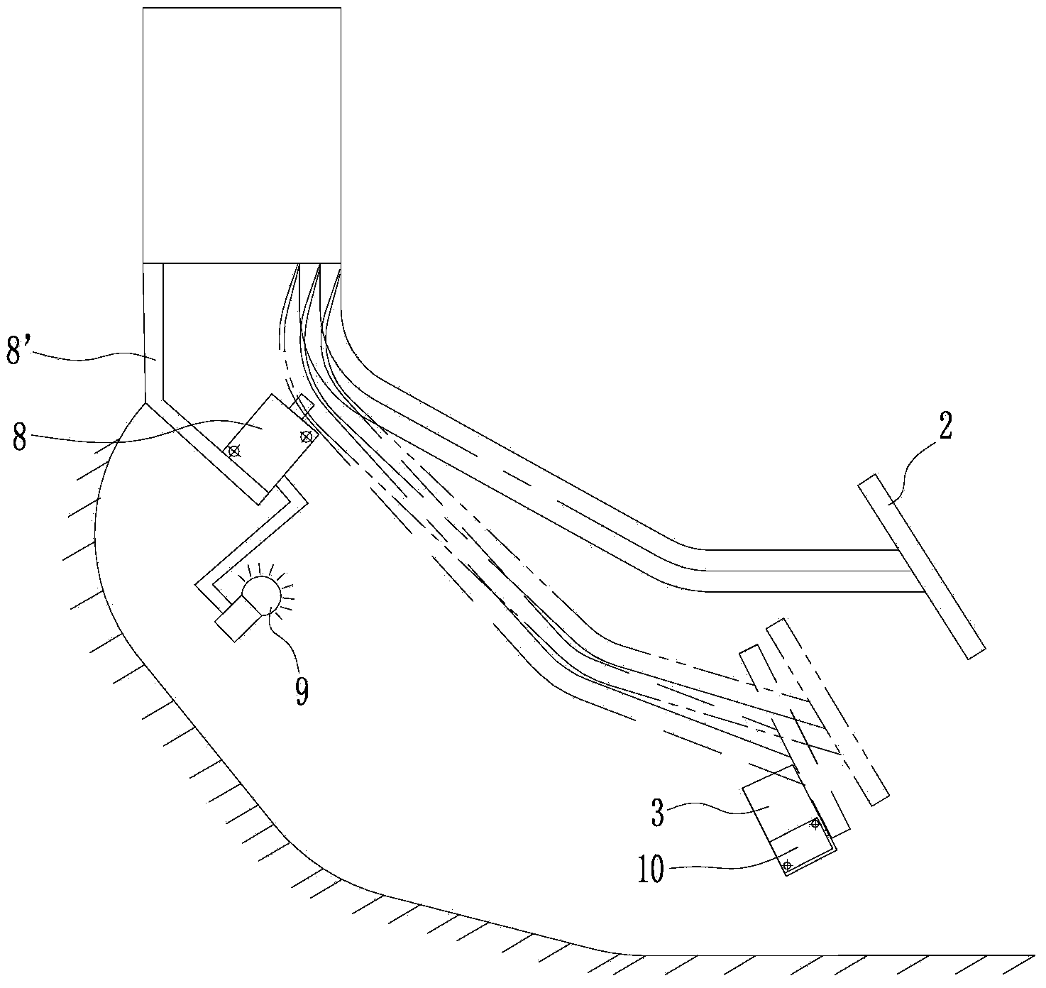
[0041] Such as figure 2 , image 3 As shown, the present embodiment does not have an accelerator linkage plate, and the accelerator limit warning switch 8 is installed on the accelerator warning switch bracket 8 ', and the contact of the accelerator limit warning switch 8 is close to the corner of the front part of the accelerator pedal 2 connecting rods. The throttle alarm switch bracket 8' is installed on the cab base plate or the throttle controller base, the throttle alarm switch bracket 8' can be connected with the cab base plate or the throttle controller base through a torsion spring, and the throttle alarm switch bracket 8' can also be formed by Spring steel sheets are bent.
[0042] Such as figure 2 , image 3As shown, the engine flameout switch 10 is installed on the transverse section of the "L" shaped brake linkage plate 7, and the contact of the engine flameout switch 10 is higher than the top surface of the brake linkage plate 7 transverse sections. Also ha...
Embodiment 3
[0050] Such as Figure 4 as shown,
[0051] In the present embodiment, the accelerator limit warning switch 8 is installed on the bottom of the rotating link plate 13, which is inclined to be high at the front and low at the rear. The upper end of the rotating link plate 13 is hinged with the top of the brake link plate 7 by rotating the positioning pin shaft 14, and a torsion spring 15 is set on the rotating positioning pin shaft 14. Another leg of spring 15 is connected with brake linkage plate 7. Described brake linkage plate 7 is fan-shaped, and the top of brake linkage plate 7 is fixed with brake pedal 1, and engine flameout switch 10 is installed at the lower end of brake linkage plate 7, and is provided with and rotates linkage plate 13 next to engine flameout switch 10 Matching force-bearing boss 7b. A plurality of limit holes are arranged at the lower end of the brake linkage plate 7 close to the arc edge, and a throttle maximum position adjustment pin 16 is insert...
PUM
 Abstract
Description
Claims
Application Information
 - R&D
- Intellectual Property
- Life Sciences
- Materials
- Tech Scout
- Unparalleled Data Quality
- Higher Quality Content
- 60% Fewer Hallucinations
Browse by: Latest US Patents, China's latest patents, Technical Efficacy Thesaurus, Application Domain, Technology Topic, Popular Technical Reports.
© 2025 PatSnap. All rights reserved.Legal|Privacy policy|Modern Slavery Act Transparency Statement|Sitemap|About US| Contact US: help@patsnap.com


