Pneumatic tire
A technology for pneumatic tires and tires, applied in tire parts, tire tread/tread pattern, transportation and packaging, etc. The effect of improving driving stability, improving ground contact, and suppressing the decrease in rigidity
- Summary
- Abstract
- Description
- Claims
- Application Information
AI Technical Summary
Problems solved by technology
Method used
Image
Examples
Embodiment approach 1
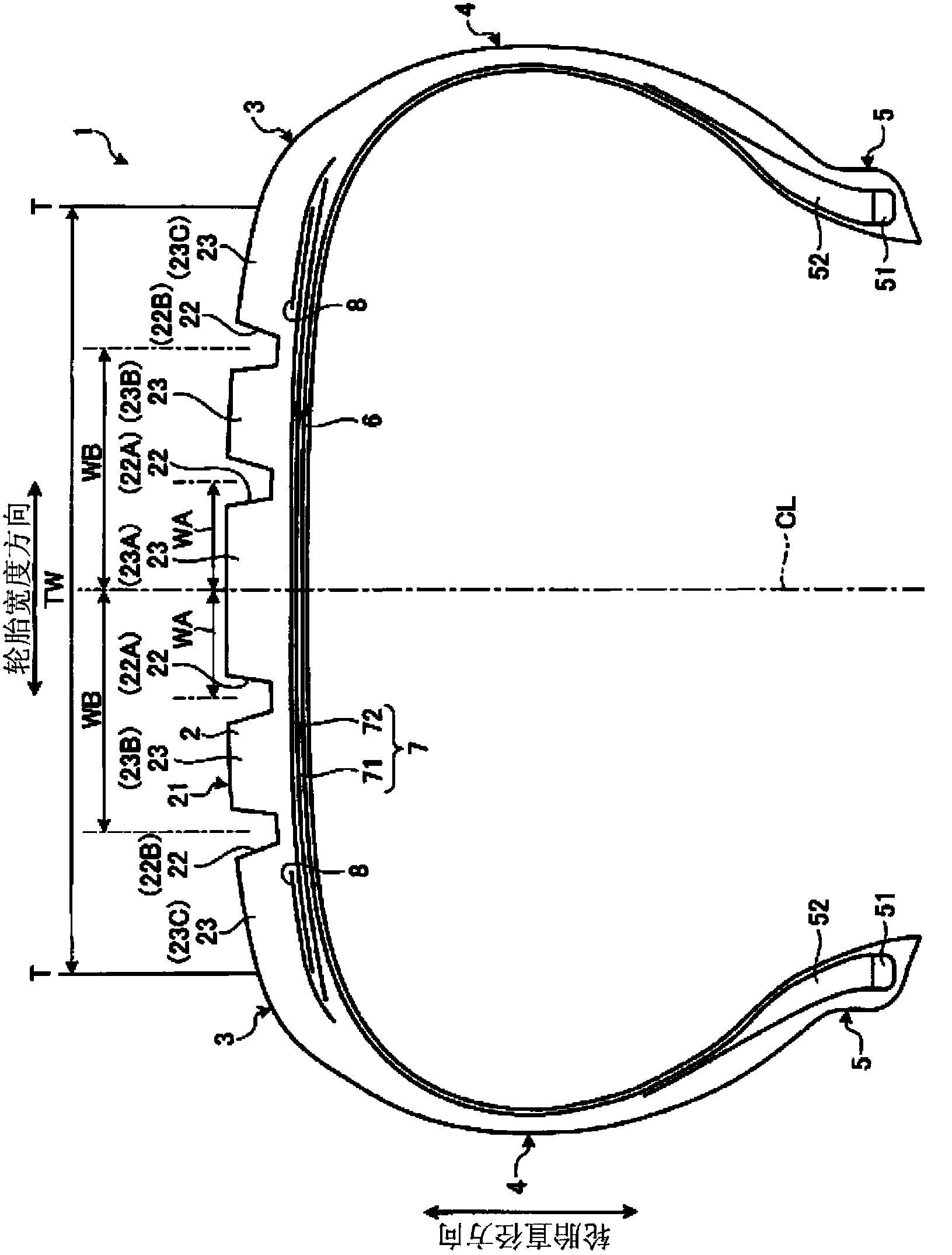
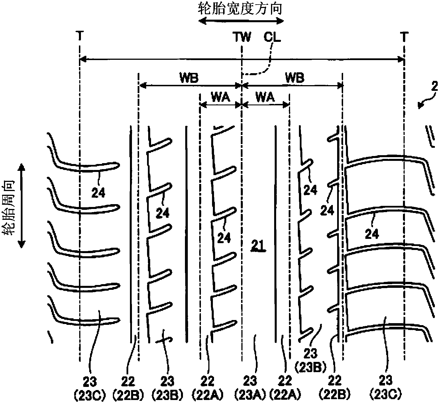
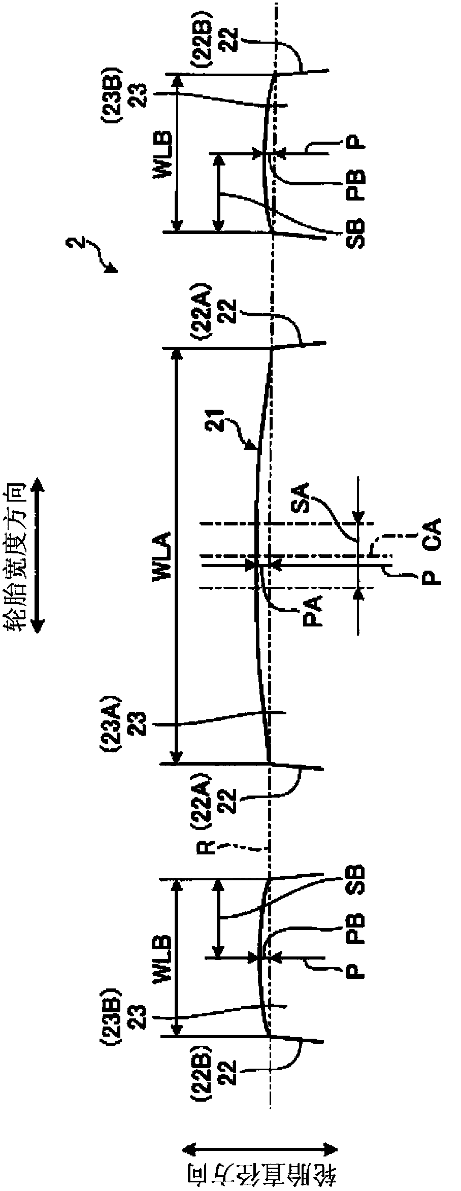
[0034] figure 1 It is a meridian sectional view of the pneumatic tire 1 according to the present embodiment, figure 2It is a plan view of the pneumatic tire according to this embodiment. In the following description, the tire radial direction refers to the direction perpendicular to the rotation axis (not shown) of the pneumatic tire 1, the tire radial inner side refers to the side close to the rotation axis in the tire radial direction, and the tire radial outer side refers to the side on the tire radial direction. The side of the tire radially away from the axis of rotation. In addition, the tire circumferential direction refers to the circumferential direction with the above-mentioned rotating shaft as the central axis. In addition, the tire width direction refers to a direction parallel to the rotation axis, the tire width direction inside refers to the side closer to the tire equatorial plane (tire equator line) CL in the tire width direction, and the tire width direct...
Embodiment approach 2
[0057] Figure 4 is a plan view of the pneumatic tire according to this embodiment, Figure 5 and Figure 6 Each is a partially enlarged meridian cross-sectional view of the tread portion of the pneumatic tire according to the present embodiment. In addition, the pneumatic tire 1 according to the present embodiment differs from the pneumatic tire 1 according to the above-mentioned first embodiment only in the structure of the central land portion 23A. Therefore, the same symbols are assigned to the same parts as those in Embodiment 1, and description thereof will be omitted.
[0058] The pneumatic tire 1 of the present embodiment, such as Figure 4 and Figure 5 As shown, the dimension WLA in the tire width direction of the center land portion 23A is set to 40 [mm] or more, and the center land portion 23A is provided with a sub-groove 25 extending in the tire circumferential direction. Here, the sub-groove 25 refers to a groove having a groove width of less than 3.0 [mm],...
Embodiment
[0071] In this embodiment, for various pneumatic tires under different conditions, performance tests related to handling stability on dry roads were carried out (refer to Figure 7 ~ Figure 9 ).
[0072] In this performance test, a pneumatic tire with a tire size of 275 / 35R20 was assembled to a normal rim (20×9J), filled with a normal internal pressure (250 [kPa]), and installed on a test vehicle with a displacement of 3500 [cc] superior.
[0073] The evaluation method of driving stability on dry roads is as follows: use the above-mentioned test vehicle to drive on a dry test road, and have a skilled test driver perform sensory tests on the handling when changing lanes and turning, and the stability when driving straight. evaluate. This sensory evaluation is expressed by an index with the pneumatic tire of the conventional example as a standard (100), and a higher index indicates better driving stability.
[0074] Figure 7 ~ Figure 9 In the pneumatic tires of Conventional...
PUM
 Abstract
Description
Claims
Application Information
 - R&D
- Intellectual Property
- Life Sciences
- Materials
- Tech Scout
- Unparalleled Data Quality
- Higher Quality Content
- 60% Fewer Hallucinations
Browse by: Latest US Patents, China's latest patents, Technical Efficacy Thesaurus, Application Domain, Technology Topic, Popular Technical Reports.
© 2025 PatSnap. All rights reserved.Legal|Privacy policy|Modern Slavery Act Transparency Statement|Sitemap|About US| Contact US: help@patsnap.com


