
Sheet laser welding clamping system

A laser welding and clamping technology, which is applied to laser welding equipment, welding equipment, welding equipment, etc., to achieve the effects of improving stability, reducing workload, and convenient operation

Active Publication Date: 2014-03-19
NANJING ZHONGKE RAYCHAM TECH
View PDF8 Cites 9 Cited by
  • Summary
  • Abstract
  • Description
  • Claims
  • Application Information

AI Technical Summary

Problems solved by technology

Through the vacuum adsorption system, the thin plate welded parts are always under uniform and relatively large negative pressure during the welding process, and prevent the thin plate from being caused by excessive heat input and output and clamping stability problems during the thin plate laser welding process. Deformation, the vacuum generated by the vacuum adsorption system can reach 88KPa, which further ensures the stability of the quality of the thin plate during the welding process

Method used


Image

  • Sheet laser welding clamping system
  • Sheet laser welding clamping system
  • Sheet laser welding clamping system

Examples


Embodiment 1

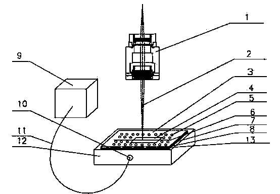
[0020] Embodiment 1: as figure 1 , Figure 4 , as shown, a thin plate laser welding clamping system, the clamping system includes a laser processing head 1, a clamp cavity base 12, and a vacuum adsorption system 9 connected to the clamp cavity base through a pipeline 11, the clamp An end cover 3 is also arranged on the base of the cavity. Through the vacuum adsorption system 9, the welded parts of the thin plate are always subjected to uniform and relatively large negative pressure during the welding process, so as to prevent problems caused by excessive heat input and output and clamping stability during the laser welding process of the thin plate. The thin plate is deformed, and the vacuum generated by the vacuum adsorption system can reach 88KPa, which further ensures the stability of the quality of the thin plate during the welding process.

Embodiment 2

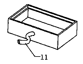
[0021] Embodiment 2: as figure 1 As shown, as an improvement of the present invention, the clamp cavity base 11 is made of high-strength steel material, and the interior is set as a cavity structure, and a through hole 10 is opened on the side wall, and the vacuum adsorption system 9 is connected with the vacuum adsorption system 9 through the pipeline 11. connect. The rest of the structures and advantages are exactly the same as in Embodiment 1.

Embodiment 3

[0022] Embodiment 3: as figure 1 , figure 2 As shown, as an improvement of the present invention, the end cap 3 is made of high-strength steel, and the middle of the end cap is opened with a groove 6 with a width of 2mm and a thickness of about 5mm, and a certain amount of circular passages are opened on both sides of the groove 6. Holes 5, two rows of through holes 5 on each side have corresponding square through holes 13 on their side walls, and are equipped with corresponding sliding catches 8, and the circular through holes 5 are controlled by the sliding of catches 8 in the corresponding square through holes 13 on and off. The rest of the structures and advantages are exactly the same as in Embodiment 1.


PUM


Abstract

The invention relates to a sheet laser welding clamping system. The sheet laser welding clamping system is characterized by comprising a laser processing head, a clamp cavity base and a vacuum absorption system, the vacuum absorption system is connected with the clamp cavity base through a pipeline, an end cover is further arranged on the clamp cavity base, the clamp cavity base is made of high-strength steel materials, a cavity structure is arranged inside the clamp cavity base, a through hole is formed in the side wall of the clamp cavity base, and the through hole is connected with the vacuum absorption device through the pipeline. The sheet laser welding clamping system has the advantages that the whole structure is simple, operation is convenient, and the cost is low; the clamp cavity base is of a cavity structure, and is connected with the upper end cover in a welding mode, the sealing effect is achieved, and the assembling structure is simple; due to the fact that the vacuum absorption system is adopted in the sheet laser welding clamping system, the degree of intelligence is greatly improved, starting and shutdown of a vacuum generator are controlled through a vacuum switch, manual operation is easy, a large number of workloads for clamping are reduced, and working efficiency is improved.

Description

technical field [0001] The invention relates to the field of laser welding, in particular to a clamping system for thin plate laser welding, which belongs to the field of laser welding. Background technique [0002] Laser welding technology has the characteristics of short action time, high efficiency, fast speed, small deformation, high weld quality, high welding precision, and easy automation. It is gradually replacing traditional welding in the fields of automobiles, trains, ships, aerospace, and machinery manufacturing. The arc welding process is widely used. [0003] With the development and promotion of various new materials, the application of thin-plate components is becoming more and more extensive, especially in the aerospace and automotive industries, for the sake of reducing weight and improving power, a large number of thin-plate structural parts are used; at the same time, with the maturity of laser technology ,Laser welding is widely used in thin plate parts,...

Claims


Application Information

Patent Timeline
Patent Type & Authority Applications(China)
IPC IPC(8): B23K26/70B23K26/21B23K37/04
CPCB23K26/24B23K26/702B23K37/0408B23K2101/18
Inventor 麻明章邢飞丁小粉迟海龙孔德旭谢德巧
Owner NANJING ZHONGKE RAYCHAM TECH
Learn More