Economical on-load tap-changer and method thereof

An on-load tapping and economical technology, applied in the direction of electronic switches, electrical components, pulse technology, etc., can solve the problems of large short-circuit circulating current, poor safety, high noise, etc., and achieve low withstand voltage requirements, simple structure, and small voltage difference Effect

Active Publication Date: 2014-03-12
SHANDONG UNIV
View PDF5 Cites 8 Cited by
  • Summary
  • Abstract
  • Description
  • Claims
  • Application Information

AI Technical Summary

Problems solved by technology

The patent US7595614 cancels the transition resistance connected in series with the thyristor circuit triggered by overvoltage; solves the heating problem of the transition resistance; since the transition resistance limiting the short-circuit circulation current is canceled, if the short-circuit circulation current occurs, the short-circuit circulation current will be very large; The response speed of the device protection is slow, so the security is poor
The patent US7595614 still uses the current transformer to trigger the bidirectional parallel thyristor to disconnect the switched current loop, and does not add new anti-interference measures, so the reliability is poor
[0004] Invention patents US4622513 and US7595614 use the secondary side current of the current transformer to trigger the bidirectional parallel thyristor switch circuit to realize the conduction and cutoff of the bidirectional parallel thyristor, and the reliability of the trigger circuit is poor
Invention patents US4622513 and US7595614 still use the traditional complex mechanical cam sliding mechanism and energy storage mechanism, which has large operating vibration and noise; it is prone to failure and cannot achieve more frequent operations
However, the converter structure proposed by the patent CN2012105791965 is not simple and economical enough

Method used


Image

  • Economical on-load tap-changer and method thereof
  • Economical on-load tap-changer and method thereof
  • Economical on-load tap-changer and method thereof

Examples


Embodiment 1

[0047] The economical on-load tap-changer consists of a selector 3 and a switch 4. The selector 4 is connected to the tap of the voltage regulating transformer, and the switcher 4 is connected to the selector 3. After the selector 3 selects the tap of the voltage regulating transformer, the switch 4 realizes the on-load switching between the two taps of the voltage regulating transformer.

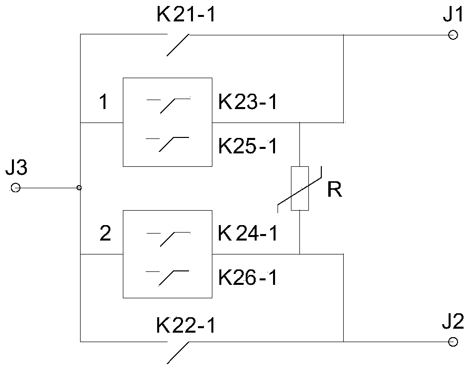
[0048] The structure and connection mode of the switcher 4 are as follows: figure 1 shown. It includes: main switch K21-1 and main switch K22-1, economical thyristor auxiliary circuit I1 and economical thyristor auxiliary circuit II2, varistor R, three terminals J1, J2, J3; terminal J1 and selector odd-numbered terminals Connection, terminal J2 is connected to the dual-number terminal of the selector, and terminal J3 is a common terminal. One end of main switch K21-1 is connected to terminal J1, and the other end is connected to terminal J3; economical thyristor auxiliary circuit I is con...

Embodiment 2

[0067] In Embodiment 1, the switches K21-1, K22-1, K23-1, K24-1, K25-1, K26-1 can be manually operated, and the switcher 4 can be realized by manually operating the electrical switches in sequence. Load switching. In fact, the switches K21-1, K22-1, K23-1, K24-1, K25-1, K26-1 can also use the mechanical linkage mechanism to drive the electrical switches to operate sequentially to realize the on-load switching of the switcher; The on-load switching of the switcher 4 can be realized by using the contactor (relay) contacts to control the sequential actions of the electrical switches; various methods can be used, and the application is flexible.

[0068]In many applications, the on-load switching of the switcher 4 is realized by controlling the switches K21-1, K22-1, K23-1, K24-1, K25-1, and K26-1 in sequence with the contacts of the contactor (relay). Simpler and more economical. The main switch K21-1 and the main switch K22-1 adopt the contactor method with locking, which is c...

Embodiment 3

[0077] The operating power of the on-load tap changer switch 4 generally comes from the local 220V low-voltage power supply. If the voltage regulating transformer is Y-connected, the transformer tap is close to the ground wire, and the voltage of the transformer tap is low; the contacts of switches K21-1, K22-1, K23-1, K24-1, K25-1, K26-1 are in contact with the operation Low voltage between power supplies. If the voltage regulating transformer coil is connected in delta, the contact voltage of switches K21-1, K22-1, K23-1, K24-1, K25-1, K26-1 is high, and the switches K21-1, K22-1, K23-1, The voltage between K24-1, K25-1, K26-1 contacts and the operating power supply is relatively high, and the switches K21-1, K22-1, K23-1, K24-1, K25-1, K26-1 contacts and operating There must be good insulation between power supplies, and high-voltage insulation materials are expensive.

[0078] This embodiment provides an economical on-load tap changer power supply with low insulation req...


PUM


Abstract

The invention relates to an economical on-load tap-changer and a method thereof. The on-load tap-changer consists of a selector and a switcher; the switcher comprises a main switch K21-1 and a main switch K22-1, an economical thyristor auxiliary circuit I and an economical thyristor auxiliary circuit II, a pressure sensitive resistor R as well as three terminals J1, J2 and J3; one end of the main switch K21-1 is connected with the terminal J1 while the other end is connected with the terminal J3; the economical thyristor auxiliary circuit I is connected with the main switch K21-1 in parallel; one end of the main switch K22-1 is connected with the terminal J2 while the other end is connected with the terminal J3; the economical thyristor auxiliary circuit II is connected with the main switch K22-1 in parallel; one end, closes to the J1, of the economical thyristor auxiliary circuit I and one end, close to the J2, of the economical thyristor auxiliary circuit II are also connected with the pressure sensitive resistor R.

Description

technical field [0001] The invention relates to the technical field of power transmission and transformation in power systems, in particular to an economical on-load tap changer and a method thereof. Background technique [0002] The operation mode of the power system changes at any time, and the change of the operation mode will cause the change of the bus voltage. The power system has strict requirements on the fluctuation range of the bus voltage, so the technology of adjusting the bus voltage is needed. It is most direct to change the way of transformer tap for voltage regulation. However, in the process of transmitting loads in the power system, changing transformer taps without power outage requires the use of very high-tech on-load tap-changers. [0003] Invention patent US4622513 uses a thyristor circuit to improve the performance of an on-load tap changer. Patent US7595614 is an improvement to US4622513. The patent US7595614 cancels the transition resistance con...

Claims


Application Information

Patent Timeline
Patent Type & Authority Applications(China)
IPC IPC(8): H03K17/687
Inventor 李晓明
Owner SHANDONG UNIV
Why Eureka
Try Eureka