
Sensor for nano gold particles and preparation method thereof

A nano-gold and sensor technology, applied in the direction of instruments, scientific instruments, measuring devices, etc., can solve problems such as difficulty in ensuring consistency, low excitation efficiency, and low repeatability

Inactive Publication Date: 2014-03-12
HARBIN ENG UNIV
View PDF10 Cites 37 Cited by
  • Summary
  • Abstract
  • Description
  • Claims
  • Application Information

AI Technical Summary

Problems solved by technology

Nano-gold particle modification also has the problem of complicated methods and difficult to ensure consistency in the air holes of photonic crystal fibers
[0009] In general, nano-gold particle sensors can be realized by the above methods, but they all have the disadvantages of low excitation efficiency, low repeatability, and complicated methods.
When using multi-mode optical fiber to modify the end surface of gold nanoparticles, the excitation efficiency is generally not high due to the direct irradiation of the light source; After treatment, it becomes very fragile, so that the repeatability of the nano-gold particle sensor made by this method is not high; the method of nano-gold particle modification in the air hole of the photonic crystal fiber also has the problem of complicated methods and difficult to ensure consistency.

Method used


Image

  • Sensor for nano gold particles and preparation method thereof
  • Sensor for nano gold particles and preparation method thereof
  • Sensor for nano gold particles and preparation method thereof

Examples


Embodiment Construction

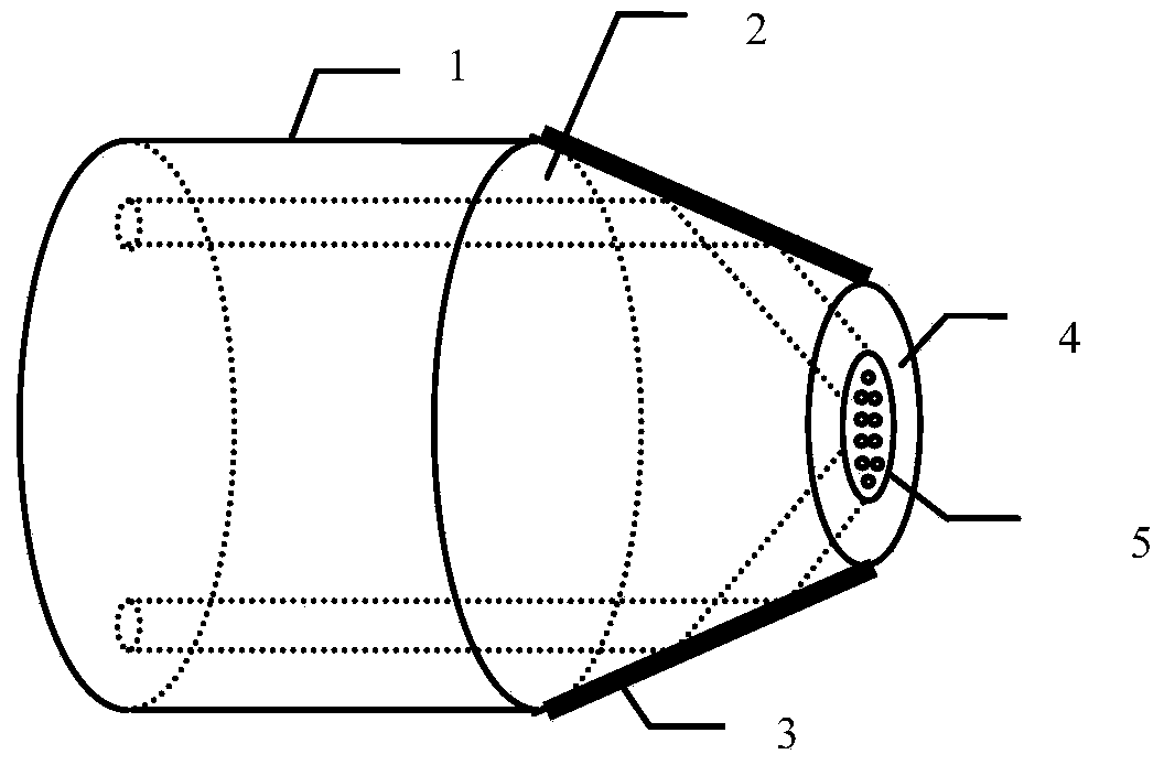
[0044] figure 1 The overall structure of the gold nanoparticle sensor is given. In the figure, 1 is a multi-core fiber whose distribution positions of multiple cores are symmetrical about the center of the fiber axis, 2 is a processed multi-core fiber end face in the shape of a frustum of a cone, 3 is a total reflection film, and 4 is a multi-core fiber coated with a reflective film. Optical fiber end face, 5 is nano gold particles.

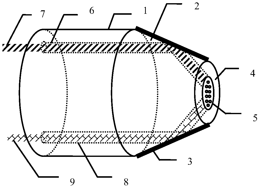
[0045] figure 2 Schematic diagram of the working principle of the gold nanoparticle sensor. In the figure, 1 is a multi-core fiber whose distribution positions of multiple cores are symmetrical about the center of the fiber axis, 2 is a processed multi-core fiber end face in the shape of a frustum of a cone, 3 is a total reflection film, and 4 is a multi-core fiber coated with a reflective film. Optical fiber end face, 5 is nano gold particles, 6 is a core of multi-core optical fiber, 7 is sensing light, 8 is reflected light to be measured, ...


PUM


Abstract

The invention provides a sensor for nano gold particles and a preparation method thereof. The end surface of a multi-core optical fiber is of a conical-platform structure; a total-reflection film is plated on the surface of the conical platform; the nano gold particles which are distributed regularly are fixed on the end surface of the optical fiber plated with the total-reflection film; exciting light is injected into one fiber core of the multi-core optical fiber, is reflected to the end surface of the optical fiber at the film-plated position of the conical platform and generates total internal reflection on the end surface of the optical fiber, and a generated evanescent field excites a localized surface plasmon resonance effect of the nano gold particles; the reflected light is collected by the fiber core symmetrical to the fiber core injected with the exciting light, and the change of the physical quantity of external substances is sensed by the spectrum of the reflecting light. The sensor and the preparation method have the advantages that the multi-core optical fiber, a self-assembly technology of a near-field optical tweezer and the localized surface plasmon resonance effect of the nano gold particles are combined, and the near-field optical tweezer of the multi-core optical fiber can be utilized for capturing the nano gold particles, so that the optical self-assembly and regular distribution is carried out on the nano gold particles according to the distribution rule of the capturing areas; the structure is simple, the volume is smaller and the repeatability is high.

Description

technical field [0001] The invention relates to an optical fiber sensor, and also relates to a preparation method of the optical fiber sensor. Specifically, it is a nano-gold particle sensor and a manufacturing method thereof. Background technique [0002] Nano-gold particles refer to tiny particles of gold with a diameter of 1-100 nm, which are generally dispersed in hydrosol. As early as the Middle Ages, gold nanoparticles have been valued by people because of their unique optical properties. Gold nanoparticles can selectively absorb specific wavelengths of visible light and present colorful colors. Nanogold materials have specific surface effects, quantum size effects, and macroscopic quantum tunneling effects, and have superior properties that conventional materials do not have in terms of electrical, magnetic, optical, and chemical properties. Therefore, it has broad application prospects in catalysis, electronic materials, micro devices, reinforcement materials and s...

Claims


Application Information

Patent Timeline
IPC IPC(8): G01N21/552
CPCG01N21/554G01N21/8507G01N2021/8528
Inventor 刘志海雷皎洁张羽赵恩铭王镭梁佩博苑立波
Owner HARBIN ENG UNIV
Learn More