Image motion compensation device and method for aerial survey of unmanned aerial vehicle

An image movement compensation, UAV technology, applied in the field of UAV aerial survey, can solve the problems of aircraft attitude influence, difficult to carry, high cost, and achieve the effect of reducing heading image movement, reducing attitude image movement, and simple structure

Active Publication Date: 2014-03-12
BEIJING SHUWEIXIANTU HIGH TECH
View PDF5 Cites 8 Cited by
  • Summary
  • Abstract
  • Description
  • Claims
  • Application Information

AI Technical Summary

Problems solved by technology

The above methods are complex in structure and high in cost, and are only suitable for large-scale aerial survey aircraft
The cameras used by small UAVs are generally finished civilian cameras, and it is difficult to change their electronic circuits; if the camera is moved backwards, the power of the backward movement, slide rails, and braking all require more energy reserves and movement space. The overall weight of the man-machine is light, the cabin is small, and it is difficult to carry
And because the inertia of the camera is very large during the backward movement, it will have a serious impact on the attitude of the aircraft

Method used


Image

  • Image motion compensation device and method for aerial survey of unmanned aerial vehicle
  • Image motion compensation device and method for aerial survey of unmanned aerial vehicle
  • Image motion compensation device and method for aerial survey of unmanned aerial vehicle

Examples


Embodiment Construction

[0027] The preferred embodiments of the present invention will be described below in conjunction with the accompanying drawings. It should be understood that the preferred embodiments described here are only used to illustrate and explain the present invention, and are not intended to limit the present invention.

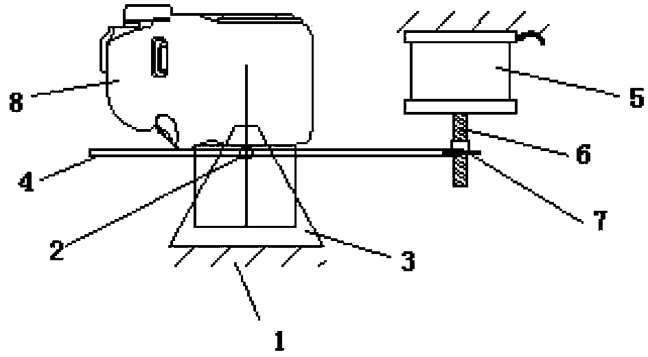
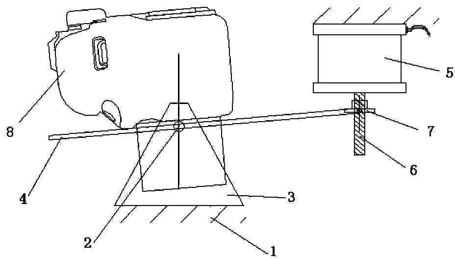
[0028] The image motion compensation device for UAV aerial survey of the present invention is only for heading image motion compensation. When the UAV is flying, because the camera is fixed on the fuselage, there will be heading image motion (the image motion caused by the pitching action is not considered temporarily) .

[0029] Such as figure 1 , 2 , 3, an image motion compensation device for unmanned aerial vehicle survey of the present invention includes a rotating shaft 2 (Ω axis) horizontally arranged in the cabin 1, the rotating shaft 2 is installed in the cabin 1 through the platform support 3, and the rotating shaft 2 Perpendicular to the axis of the fuse...


PUM


Abstract

The invention discloses an image motion compensation device for aerial survey of an unmanned aerial vehicle. The image motion compensation device comprises a rotary shaft horizontally arranged in a cabin and perpendicular to an axis of the fuselage, a camera installation platform mounted on the rotary shaft and capable of rotating around the rotary shaft, and a motor for connection with a flight control computer of the unmanned aerial vehicle, wherein the motor is connected with the camera installation platform. The image motion compensation device has the characteristics of small volume, light weight, simple structure and low energy consumption, and can be conveniently applied to the unmanned aerial vehicle. The invention also discloses an image motion compensation method for aerial survey of the unmanned aerial vehicle. The flight control computer of the unmanned aerial vehicle controls the motor to drive the camera installation platform to form a certain angular velocity around the rotary shaft, so that the camera is driven to rotate, and the optical axis of the camera locks (follows) a certain point on the ground. When the optical axis of the camera is vertical to the bottom of the cabin, the shutter is initiated to take a photo; and at the same time, the camera installation platform continuously rotates at the angular velocity at least until the completion of the photo taking. The above method can reduce the course image motion during aerial survey of the unmanned aerial vehicle and improve the measurement accuracy.

Description

technical field [0001] The present invention relates to the field of aerial survey of unmanned aerial vehicles, in particular to an image motion compensation device and method for aerial survey of unmanned aerial vehicles. Background technique [0002] With the development of UAV technology, UAV aerial survey technology has been widely used. In the process of aerial survey, due to the relatively low flight altitude (generally 300-1000 meters) and fast speed (generally 30 m / s) of the UAV, most of the cameras used are civilian SLR cameras, which are generally fixed on the aircraft. On the body, the shutter speed is about 1 / 1000th of a second. In the process of aerial photography, the camera will produce a large image motion in the forward direction at the moment of exposure, generally accounting for 1 / 3 to 1 pixel, resulting in a sharp increase in measurement error. In addition, the UAV is based on the airspeed during the flight, and is affected by the wind speed and wind di...

Claims


Application Information

Patent Timeline
IPC IPC(8): G01C11/02G01C25/00
CPCG01C11/00
Inventor 董韬白瑞杰
Owner BEIJING SHUWEIXIANTU HIGH TECH
Why Eureka
Try Eureka