Rotary cement kiln waste-heat utilization heat exchanger with multiple soot blowing openings and soot blowing method thereof

A cement rotary kiln and heat exchanger technology, applied in indirect heat exchangers, heat exchanger types, combustion methods, etc., can solve problems such as fouling, achieve strong heat transfer capacity, good soot blowing effect, and meet heat transfer requirements. and the effect of reducing dust accumulation

Inactive Publication Date: 2014-09-10
SHANDONG UNIV
View PDF3 Cites 0 Cited by
  • Summary
  • Abstract
  • Description
  • Claims
  • Application Information

AI Technical Summary

Problems solved by technology

[0005] Aiming at the problem of serious ash accumulation existing in existing cement rotary kiln tail gas utilization heat exchange equipment, the present invention proposes a cement rotary kiln waste heat utilization heat exchanger which is not easy to ash accumulation and has good soot blowing effect and has multiple soot blowing ports. A soot blowing method for the heat exchanger is provided

Method used


Image

  • Rotary cement kiln waste-heat utilization heat exchanger with multiple soot blowing openings and soot blowing method thereof
  • Rotary cement kiln waste-heat utilization heat exchanger with multiple soot blowing openings and soot blowing method thereof
  • Rotary cement kiln waste-heat utilization heat exchanger with multiple soot blowing openings and soot blowing method thereof

Examples


Embodiment Construction

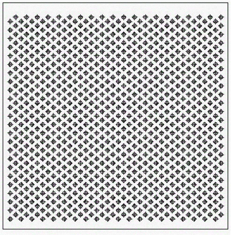
[0043] The diamond-shaped arrangement of heat exchange tube bundles described in the following content (the heat exchange tube bundle is composed of several heat exchange tubes) and the diamond-shaped structure of the shell are the shapes viewed from the section perpendicular to the central axis of the heat exchange tube bundle; the heat exchange tube spacing is Refers to the distance between the central axes of adjacent heat exchange tubes.

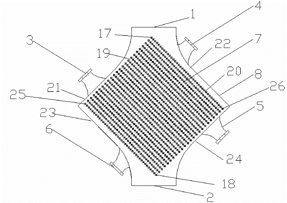
[0044] Such as image 3 As shown, the heat exchanger of the present invention includes a heat exchange tube bundle 7 , an exhaust gas inlet 1 , an exhaust gas outlet 2 and a shell 8 . The heat exchange tube bundle 7 is arranged in the shell 8, and the heat exchange tube bundle is arranged in a rhombus shape, and the first side 19 of the rhombus arrangement of the heat exchange tube bundle is adjacent to the second side 20 of the rhombus arrangement of the heat exchange tube bundle, as Figure 4 As shown, the first side 19 and the second...


PUM


Abstract

The invention discloses a rotary cement kiln waste-heat utilization heat exchanger with multiple soot blowing openings and a soot blowing method of the rotary cement kiln waste-heat utilization heat exchanger. The rotary cement kiln waste-heat utilization heat exchanger with the multiple soot blowing openings comprises a heat exchange tube bundle, a tail gas inlet, a tail gas outlet and a casing, wherein the heat exchange tube bundle is arranged inside the casing, the heat exchange tube bundle is arranged in a rhombus form, the casing adopts a rhombic structure matched with the rhombus form of the heat exchange tube bundle, and is namely a rhombic casing, the tail gas inlet is arranged in the position of a first included angle of the rhombic casing, the tail gas outlet is arranged in the position of a second included angle of the rhombic casing, and soot blowing openings are arranged on all edges of the rhombic casing; the soot blowing openings are connected with a soot blowing pipeline, a fan is connected to the interior of the soot blowing pipeline and is connected with a central controller, and the central controller is used for controlling the frequency of the fan through computing the thermal-conduction resistance of the heat exchange tube bundle. The heat exchange tube bundle is arranged in the rhombus form, and has the characteristics of low probability of soot formation, good soot blowing effect, strong heat-transfer capability and the like, and through opening and closing the multiple soot blowing openings, soot blowing can be performed in different directions. Therefore, the good soot blowing effect of the heat exchanger can be achieved.

Description

technical field [0001] The invention relates to a high-efficiency heat exchanger and a soot blowing method for utilization of waste heat from tail gas of a cement rotary kiln, and belongs to the technical field of heat exchangers for waste heat utilization. Background technique [0002] With the rapid development of my country's economy, energy consumption is increasing day by day, and the problem of deteriorating urban air quality is becoming more and more prominent. It is urgent to save energy and reduce the emission of harmful environmental substances. In the common thermal power field, one of the main reasons for high energy consumption and serious pollution is that the exhaust gas temperature of the flue gas is too high, which wastes a lot of energy and causes environmental pollution. The cement industry is a high energy consumption and high pollution industry. The tail gas produced by cement rotary kiln has high dust concentration and poor quality. The waste heat pow...

Claims


Application Information

Patent Timeline
Patent Type & Authority Patents(China)
IPC IPC(8): F28D7/16F28F1/12F23J3/00F27D17/00
CPCY02P10/25Y02P80/15
Inventor 程林杜文静王乃华
Owner SHANDONG UNIV
Why Eureka
Try Eureka