Variable-torque driven shaft

A driven shaft and central shaft technology, applied in the field of driven shaft design, can solve the problems of loose and broken materials, affecting the normal production progress, etc., and achieve the effect of maintaining tension and stability, and stable speed

Inactive Publication Date: 2014-03-12
吴中区甪直渡岘工艺品厂
View PDF5 Cites 0 Cited by
  • Summary
  • Abstract
  • Description
  • Claims
  • Application Information

AI Technical Summary

Problems solved by technology

Ordinary driven shafts do not have torque stabilizing devices. Due to inertia and the pulling of the coiler, the coiled materials are likely to loosen and break, affecting the normal progress of production.

Method used


Image

  • Variable-torque driven shaft

Examples


Embodiment Construction

[0012] The technical solutions in the embodiments of the present invention will be described clearly and completely below. Obviously, the described embodiments are only a part of the embodiments of the present invention, rather than all the embodiments. Based on the embodiments of the present invention, all other embodiments obtained by those of ordinary skill in the art without creative work shall fall within the protection scope of the present invention.

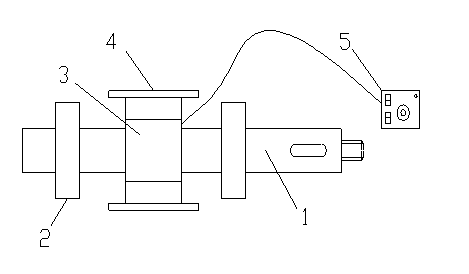
[0013] See figure 1 , The embodiment of the present invention includes:

[0014] A variable torque driven shaft, comprising: a central shaft body 1, a support bearing 2, an electromagnetic coil 3, a fixed base 4, and a torque controller 5. The central shaft body 1 passes through the center position of the electromagnetic coil 3. The inner diameter size of the support bearing 2 is the same as the outer circle size of the central shaft body, and it is closely matched. The number of the support bearing 2 is two, which are located...


PUM


Abstract

The invention discloses a variable-torque driven shaft, which comprises a central shaft body, supporting bearings, an electromagnetic coil, a fixed base and a torque controller, wherein the central shaft body penetrates through the central position of the electromagnetic coil; the inner diameter of each supporting bearing is the same with the diameter of the outer circle of the central shaft body; the number of the supporting bearings is two; the two support bearings are separately arranged at the two lateral sides of the electromagnetic coil; the outer circle of the electromagnetic coil is connected with the fixed base; the torque controller and the electromagnetic coil are in linear connection. By adopting the manner, during rotating, the variable-torque driven shaft utilizes the constant resistance given by the electromagnetic coil to the central shaft body, the torque is adjustable and the rotating speed is smoother under the driving of a rolling machine, so that the rolled matters have certain tension and stability.

Description

Technical field [0001] The invention relates to the design field of a driven shaft of a coiling machine, in particular to a variable torque driven shaft. Background technique [0002] In trademark, printing, weaving, tape and other industries, it is necessary to use the coiling machine to rewind the product or unwind the raw material. In the process of coiling, in order to prevent the rolled material from wrinkling, loosening or breaking, the coiling machine is often required to have a certain speed and tension during operation, thereby improving the quality of the coil. [0003] The material rod of the coiler is generally actively rotating, and the cooperation of the driven shaft is required during use. The ordinary driven shaft does not have a torque stabilization device. Due to inertia and the pulling of the coiler, the rolled materials are likely to loose and break, which affects the normal progress of production. Summary of the invention [0004] The main technical problem so...

Claims


Application Information

Patent Timeline
Patent Type & Authority Applications(China)
IPC IPC(8): F16C3/02
Inventor 吴丹
Owner 吴中区甪直渡岘工艺品厂
Why Eureka
Try Eureka