
Electronic metering filling machine

An electronic measurement and filling machine technology, applied in bottle filling, packaging, liquid bottling, etc., can solve the problems of limiting the applicability of filling operations, and achieve the effects of improving production efficiency and accurate measurement control

Active Publication Date: 2015-12-16
江苏普华盛包装科技有限公司
View PDF6 Cites 0 Cited by
  • Summary
  • Abstract
  • Description
  • Claims
  • Application Information

AI Technical Summary

Problems solved by technology

The quantitative nature of these two methods of filling often limits the versatility of filling operations

Method used


Image

  • Electronic metering filling machine
  • Electronic metering filling machine

Examples


specific Embodiment 1

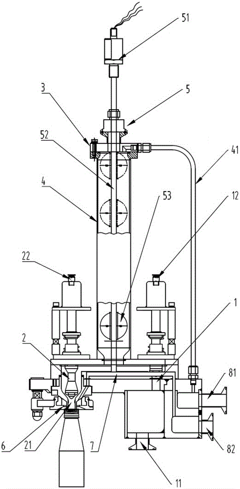
[0015] Specific embodiment one, carry out the filling operation, set the upper and lower limit positions of the floating ball displacement according to the filling volume, set the corresponding threshold value on the electronic controller according to the upper and lower limit positions of the floating ball and the electrical signal of the metering rod, Initially, the filling valve is open and the filling valve is closed. The material is injected through the injection port, the material enters the transition cavity through the injection channel and the material channel, the material supports the floating ball, and as the floating ball rises, the electrical signal of the metering rod increases slowly, and the air in the transition cavity is discharged through the return air pipe , when the electrical signal value reaches the corresponding threshold value of the electronic controller, the electronic controller drives the injection valve to close and the filling valve to open, and...

specific Embodiment 2

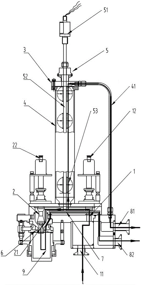
[0017] Specific embodiment two, such as figure 2 As shown, the arrow path is the CIP positioning and cleaning path. To perform the cleaning operation, set the cleaning cup cover on the filling port, turn off the electronic liquid level gauge at the same time, open the filling valve and the filling valve, and then inject the cleaning liquid from the filling port. The cleaning liquid is divided into two ways to clean the filling machine, one of which is along the injection channel and material channel to the transition chamber, then from the transition chamber to the air return pipe, and finally discharged from the return chamber of the air return pipe; the other is along the injection channel and the material After the passage to the filling passage, it is divided into two strands, one enters the cleaning cup to clean the filling port and its periphery, and the other strand is discharged along the return cavity of the positioning and cleaning return passage after being position...


PUM


Abstract

The invention discloses an electronic metering and filling machine. According to the electronic metering and filling machine, a material injection channel and a filling channel are arranged along a material channel; the material injection channel is provided with a material injection port and a material injection valve; the filling channel is provided with a filling port and a filling valve. Particularly, according to the electronic metering and filling machine, an electronic metering valve is arranged in the material channel between the material injection valve and the filling valve, and consists of a transitional cavity and an electronic liquid level meter; a gas return pipe is arranged on the top of the transitional cavity; the electronic liquid level meter is provided with an electronic controller and a metering rod which penetrates through the transitional cavity; a floating ball which is slidably sleeved is arranged at the section, in the transitional cavity, of the metering rod; and the electronic controller drives and controls the turn-on and turn-off of the material injection valve and the filling valve. According to the electronic metering and filling machine, the electronic metering valve is used for driving the material injection valve and controlling the filling amount of the filling valve; by the lifting of the floating ball on the metering rod, an electric signal is generated, and the electronic controller drives the material injection valve or the filling valve to work according to the electric signal, so that the entire metering control is accurate, the filling steps are coherent, and the production efficiency is improved.

Description

technical field [0001] The invention relates to a filling machine, in particular to an electronic metering filling machine. Background technique [0002] The beverage filling machine will involve steps such as filling, metering, and filling in the filling process, and the meter used in the metering step is directly related to the accuracy and efficiency of filling. [0003] There are usually two ways for filling valves to quantify liquid material bottling: one is positioning filling, and the other is quantitative filling. The quantitative nature of these two methods of filling often limits the applicability of filling operations. In the actual production process of filling beverages, one piece of equipment is often used for filling with different capacities. For this reason, a design requirement is put forward for the adjustability of the filling volume of the filling machine, and this adjustability needs to be simple and easy to control. Contents of the invention [00...

Claims


Application Information

Patent Timeline
Patent Type & Authority Patents(China)
IPC IPC(8): B67C3/26B67C3/28
Inventor 顾平黄磊
Owner 江苏普华盛包装科技有限公司
Learn More