
Steel coil hoisting tool

A hoisting and tooling technology, applied in the direction of transportation and packaging, load hanging components, etc., can solve the problems of potential safety hazards, low hoisting efficiency, steel coil cuts, etc., to achieve safe and reliable hoisting process, improve hoisting efficiency, coordination and Simple and quick effect of disassembly process

Inactive Publication Date: 2014-03-12
TIANJIN JINWANFANG STEEL STRUCTURE
View PDF4 Cites 10 Cited by
  • Summary
  • Abstract
  • Description
  • Claims
  • Application Information

AI Technical Summary

Problems solved by technology

[0002] Color steel coils and steel strips are indispensable production materials in the manufacture and construction of steel structures. The weight of a whole coil of color steel coils or steel strips weighs several tons. In the prior art, there is no special hoisting, The spreader for loading and unloading color steel coils and steel strip coils, the production site uses ordinary hooks to hang steel wire ropes to lift the color steel coils and steel strip coils. This simple spreader has the following disadvantages: 1. Damage to the steel coils : Due to the huge single weight of the steel coil and the thin steel wire rope, when lifting, the two ends of the inner ring of the steel coil are under too much force, and the steel wire rope will cut the steel coil, causing unnecessary loss of the steel coil
2. There are potential safety hazards: the thinner wire rope will rub against the steel coil for a long time, and it is easy to break and break. Once the wire rope is damaged and broken, several tons of steel coils will fall, and the consequences will be disastrous
3. Low hoisting efficiency: the process of binding steel coils with wire ropes is time-consuming and laborious

Method used


Image

  • Steel coil hoisting tool

Examples


Embodiment Construction

[0010] In order to further understand the invention content, characteristics and effects of the present invention, the following examples are given, and detailed descriptions are as follows in conjunction with the accompanying drawings:

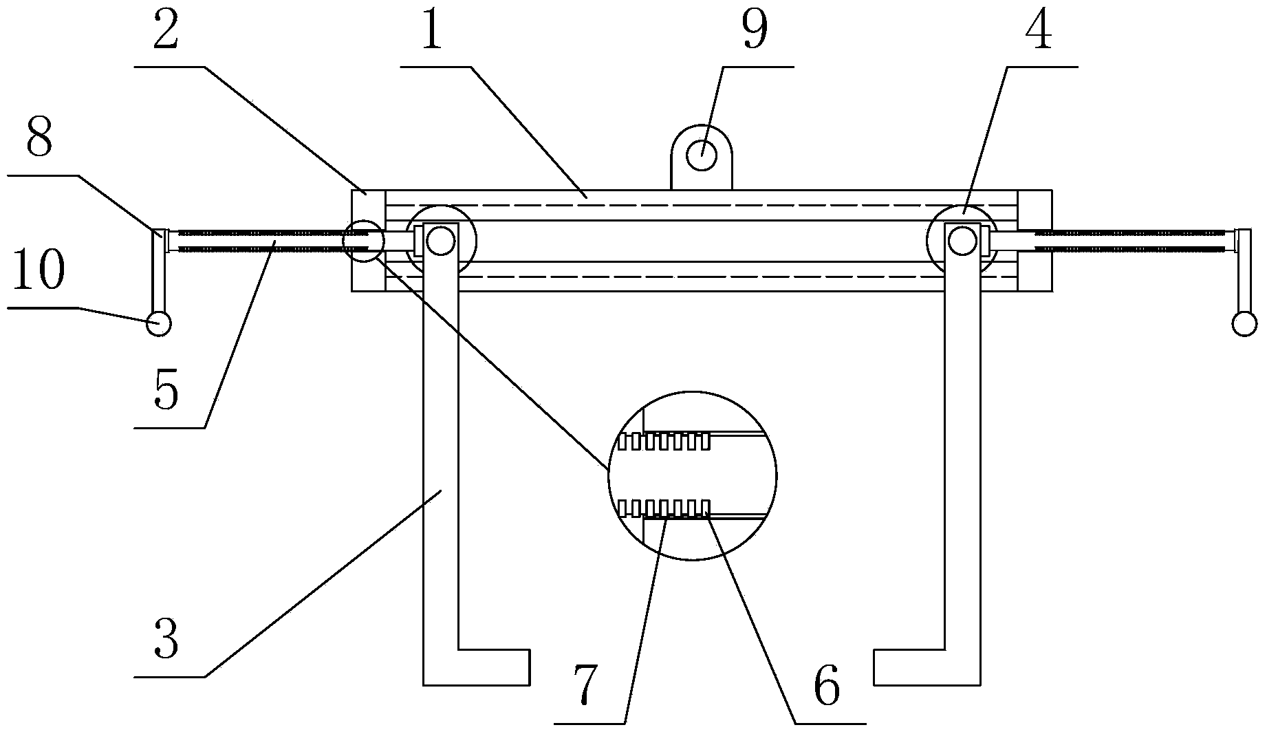
[0011] see figure 1 , a steel coil hoisting tool, comprising two parallel hoisting beams 1 and end plates 2 respectively located at both ends of the hoisting beams 1 for connecting the two hoisting beams 1, in this embodiment, the two hoisting beams 1 and the two The bar end plate 2 is welded to form a rectangular frame, and the hoisting beam 1 is a c-shaped steel with long grooves on it. The long slots of the two hoisting beams 1 are opposite, and two L-shaped hangers 3 are arranged between the two hoisting beams 1, and the L-shaped hangers 3 are respectively embedded in the lengths of the two hoisting beams 1 The rollers 4 in the groove are installed between the two hoisting beams 1 , the two rollers 4 are coaxial, and the L-shaped hanger ...


PUM


Abstract

The invention relates to a steel coil hoisting tool which comprises two parallel hoisting beams and end plates, wherein the end plates are used for connecting the two hoisting beams and are respectively positioned at both ends of the hoisting beams; each hoisting beam is a c-shaped steel with a long slot; the long slots of the two hoisting beams are opposite; two L-shaped hangers are arranged between the two hoisting beams; the L-shaped hangers are mounted between the two hoisting beams through rollers respectively embedded in the long slots of the two hoisting beams; two rollers are coaxial; through holes are respectively formed in the two end plates; push-pull rods in parallel to the hoisting beams are respectively inserted in the through holes; a plurality of latches are uniformly distributed on the push-pull rods in the axial direction; clamping grooves matched with the latches are formed in the inner sides of the through holes; the two push-pull rods are respectively connected with the two L-shaped hangers; handles perpendicular to the push-pull rods are mounted at the end parts outside the push-pull rods. The steel coil hoisting tool has the advantages of simple structure, convenience in use, firm structure, avoidance for damage to a steel coil, improvement on hoisting efficiency and elimination for potential safety hazards.

Description

technical field [0001] The invention belongs to the technical field of hoisting equipment, in particular to a steel coil hoisting equipment. Background technique [0002] Color steel coils and steel strips are indispensable production materials in the manufacture and construction of steel structures. The weight of a whole coil of color steel coils or steel strips weighs several tons. In the prior art, there is no special hoisting, The spreader for loading and unloading color steel coils and steel strip coils, the production site uses ordinary hooks to hang steel wire ropes to lift the color steel coils and steel strip coils. This simple spreader has the following disadvantages: 1. Damage to the steel coils : Because the single weight of the steel coil is huge and the steel wire rope is relatively thin, when lifting, the two ends of the inner ring of the steel coil are under too much force, and the steel wire rope will form cuts on the steel coil, causing unnecessary loss of ...

Claims


Application Information

Patent Timeline
IPC IPC(8): B66C1/22B66C1/44
Inventor 张振海
Owner TIANJIN JINWANFANG STEEL STRUCTURE
Learn More