A buoyancy element, riser assembly including a buoyancy element and a method of supporting a riser

A technology of buoyancy components and tube components, which is applied in the direction of drill pipes, casings, buoys, etc., and can solve problems such as moving troubles and energy consumption

Inactive Publication Date: 2014-03-05
GE OIL & GAS UK LTD
View PDF5 Cites 1 Cited by
  • Summary
  • Abstract
  • Description
  • Claims
  • Application Information

AI Technical Summary

Problems solved by technology

However, moving this piece of equipment (especially at any speed) always proves to be cumbersome and energy-intensive

Method used


Image

  • A buoyancy element, riser assembly including a buoyancy element and a method of supporting a riser
  • A buoyancy element, riser assembly including a buoyancy element and a method of supporting a riser
  • A buoyancy element, riser assembly including a buoyancy element and a method of supporting a riser

Examples


Embodiment Construction

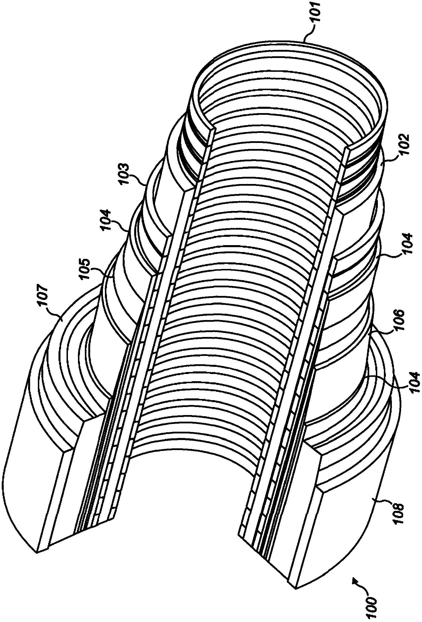
[0033] In this specification, flexible pipes will be introduced. It is to be understood that a flexible pipe is an assembly of a portion of a pipe body and one or more end fittings in each end fitting in which a respective end of the pipe body terminates. figure 2 Illustrated is the manner in which the tubular body 100 is formed from a combination of layered materials forming a pressure-bearing conduit according to one embodiment of the invention. although figure 2 A number of specific layers are shown in , it being understood that the invention is broadly applicable to coaxial tubular body structures comprising two or more layers fabricated from a wide variety of possible materials. Note also that layer thicknesses are shown for illustration purposes only.

[0034] Such as figure 2 As shown, the tubular body includes an optional innermost carcass layer 101 . The carcass provides an interlocking structure that can act as an innermost layer, fully or partially preventing...


PUM


Abstract

A buoyancy element, riser assembly including a buoyancy element and a method of supporting a riser are disclosed. The buoyancy element (400) includes a body (402) of at least partly flexible structure having a volume that is adjustable between an expanded and contracted position, and an entry port (404) for fluid to be supplied to and / or removed from the body to thereby adjust the volume of the body.

Description

technical field [0001] The present invention relates to a buoyancy element, a riser assembly including the buoyancy element and a method of supporting a riser. In particular but not exclusively, the present invention relates to a riser assembly suitable for use in the oil and gas industry. Background technique [0002] Conventional flexible pipes are used to transport production fluids such as oil and / or gas and / or water from one location to another. Flexible pipe is particularly useful in connecting a subsea location (which may be a deep water location) to a sea level location. Flexible pipe is generally formed as an assembly of a flexible pipe body and one or more end fittings. The pipe body is generally formed as a combination of layered materials forming a pressure-containing conduit. The tube structure allows for large deflections without creating bending stresses that impair the tube's functionality over its lifetime. The pipe body is generally constructed as a com...

Claims


Application Information

Patent Timeline
Patent Type & Authority Applications(China)
IPC IPC(8): B63B22/18E21B17/01
CPCE21B17/012B63B22/20B63B22/00B63B22/18E21B17/015F16L1/24
Inventor 约翰·罗舍
Owner GE OIL & GAS UK LTD
Why Eureka
Try Eureka