Supercharge Your Innovation With Domain-Expert AI Agents!

Pedal valuator arrangement

A pedal sensor and pedal technology, applied in the direction of mechanical control devices, foot activation devices, brake action activation devices, etc., can solve the problems of limiting and increasing the risk of driver's foot injury, injury, etc., and achieve the effect of simple structure

Inactive Publication Date: 2014-03-05
ROBERT BOSCH GMBH
View PDF4 Cites 2 Cited by
  • Summary
  • Abstract
  • Description
  • Claims
  • Application Information

AI Technical Summary

Problems solved by technology

This increases the risk of injury to the driver's feet
In particular, the pedals protruding into the footwell lead to an even more restricted position and thus lead to additional injuries in the event of an accident

Method used


Image

  • Pedal valuator arrangement
  • Pedal valuator arrangement
  • Pedal valuator arrangement

Examples


Embodiment Construction

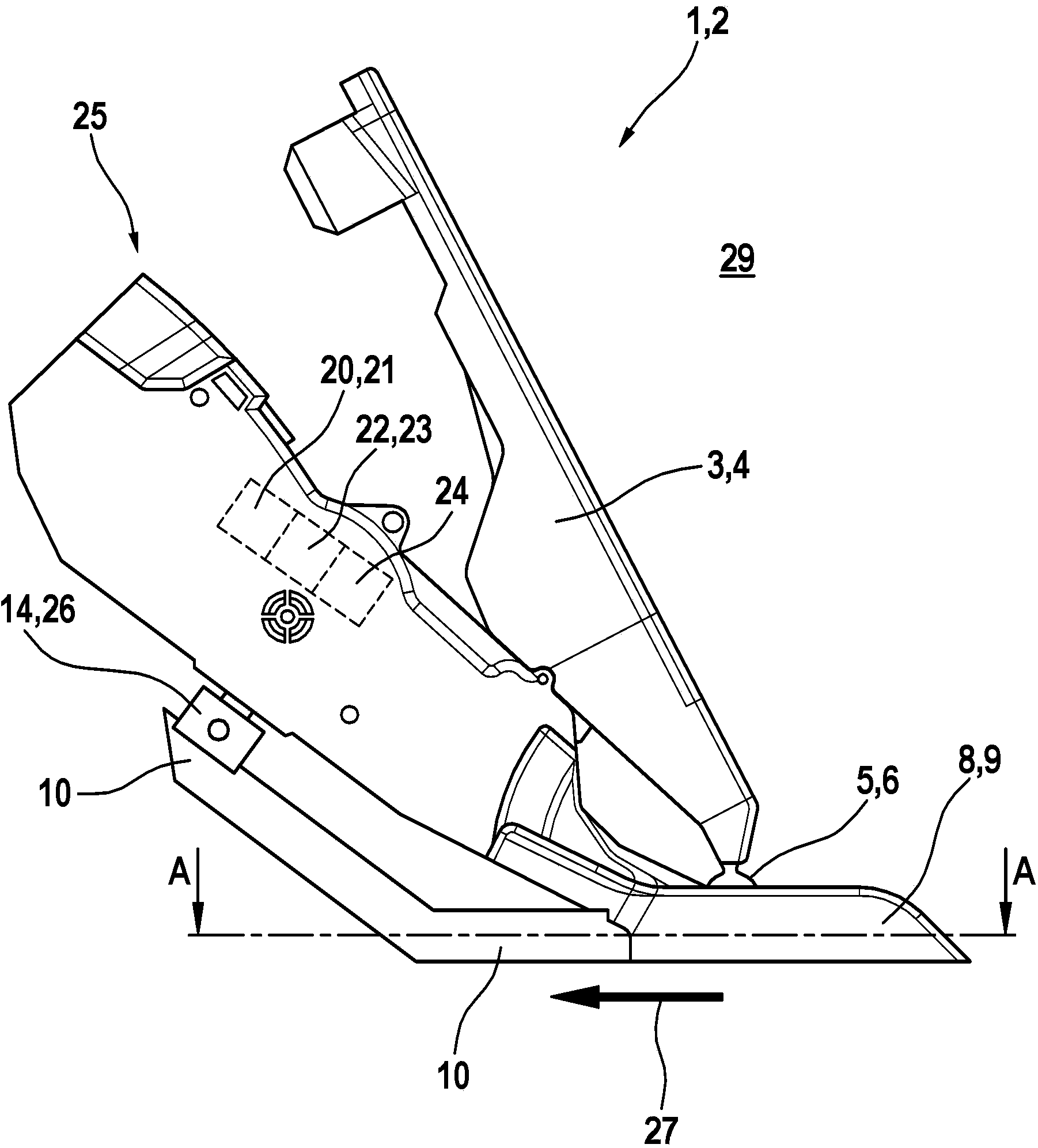
[0030]The pedal sensor device 2 is installed as the pedal device 1 in a motor vehicle 28 having a not shown internal combustion engine or an electric motor as the drive motor to control and / or regulate the power of the drive motor by means of an electronic accelerator system. For this purpose, sensor 24 detects the position of pedal 3 as accelerator pedal or accelerator pedal 4 , and the power of the drive engine of motor vehicle 28 is controlled and / or regulated as a function of the position of accelerator pedal 4 . In the case of an internal combustion engine as the drive motor, the throttle mechanism, such as a throttle valve, is moved, for example, with a servomotor; in the case of an electric motor as the drive motor, the throttle mechanism controls and / or regulates (not shown) the Electric power.

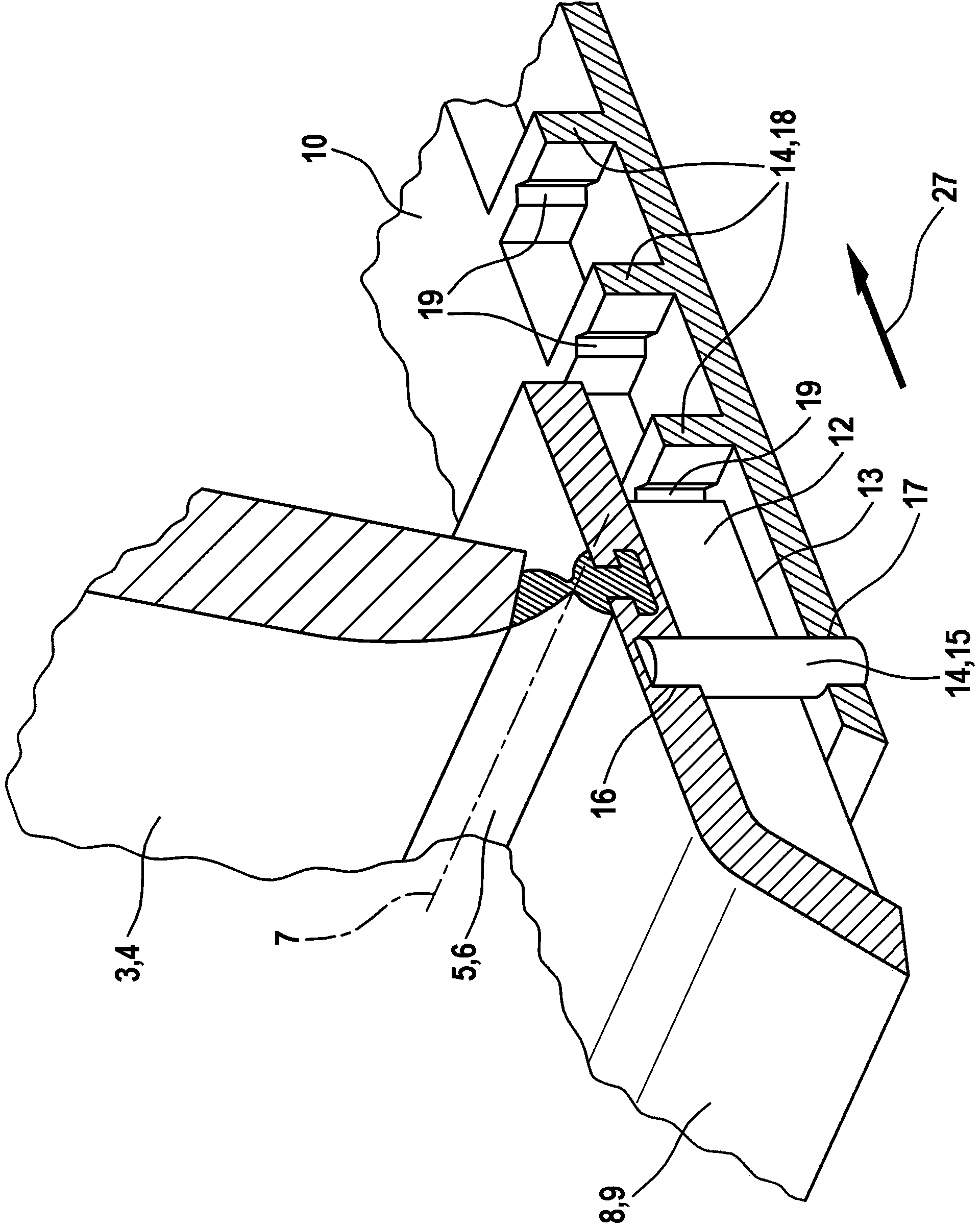
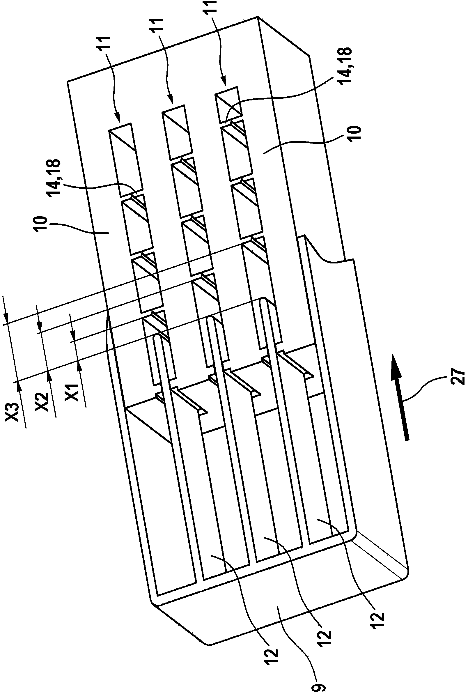
[0031] Pedal 3 is pivotably supported on a bearing 5 as a film hinge 6 around an axis of rotation 7 ( figure 2 ). By means of the foot of the driver of the motor vehicle 28...


PUM


Abstract

Pedal arrangement (1), in particular pedal valuator arrangement (2) for a motor vehicle, comprising a pedal (3), in particular An accelerator pedal (4), which is movable between an initial position and an end position, a bearing (5) for the pedal (3), a bearing part (8), on which the bearing (5) is arranged, and a device (9) for moving the pedal (3) forwards in the event of an accident, wherein the bearing part (8) is in the form of a movable carriage (9), with the result that, in the event of an accident, the carriage (9) together with the bearing (5) and the pedal (3) is movable forwards from a driving position into an accident position.

Description

technical field [0001] The invention relates to a pedal arrangement according to the preamble of claim 1 . Background technique [0002] Pedal devices with an accelerator or accelerator pedal, in particular pedal sensor devices, are used in motor vehicles to control the power or operating profile of the motor vehicle's drive engine. Here, pedals are arranged in the lower area of ​​the footwell for control with the driver's feet. In the event of an accident, the driver generally protects the head or chest from injury by means of a passenger restraint system, such as a seat belt or an air bag. In the event of an accident, the passenger compartment is pushed under the dashboard by the engine block and thus reduces the usable footwell. This increases the risk of injury to the driver's feet. In particular, the pedals protruding into the footwell lead to an even more restricted position and thus lead to additional injuries in the event of an accident. For this reason, it is al...

Claims


Application Information

Patent Timeline
Patent Type & Authority Applications(China)
IPC IPC(8): B60K26/02B60T7/06
CPCB60K2026/024B60R21/09B60T7/065B60K28/14G05G1/30B60K26/02B60T7/06
Inventor V·齐泽克
Owner ROBERT BOSCH GMBH
Features
  • R&D
  • Intellectual Property
  • Life Sciences
  • Materials
  • Tech Scout
  • Unparalleled Data Quality
  • Higher Quality Content
  • 60% Fewer Hallucinations
Learn More