Modularized thyristor valve block for solid combination switch device

A technology of thyristor valve and compound switch, which is applied to electronic switches, electro-solid devices, electrical components, etc., can solve the problems of a large number of high-frequency energy-transmitting devices, difficult installation of plug-in terminals, and a large amount of processing and installation. Small, consistent, and low-cost effects

Inactive Publication Date: 2014-03-05
STATE GRID CORP OF CHINA +1
View PDF5 Cites 7 Cited by
  • Summary
  • Abstract
  • Description
  • Claims
  • Application Information

AI Technical Summary

Problems solved by technology

[0006] 1. It can only meet the requirements of 10kV level, and it needs to be redesigned under other voltage level systems;
[0007] 2. Each string of thyristors inside the valve group is pressed and fixed by four rod-shaped insulating rods. The installation is complex and cumbersome, and the cost is high;
[0008] 3. The installation box of the high-potential control board (TE board) has poor shielding and protection effects, and the plug-in terminals are not easy to install;
[0009] 4. Each high-potential control board (TE board) requires a set of high-frequency (5kHz) energy transmission devices (CT), which require a large number of high-frequency energy transmission devices (CT), a large amount of processing and installation, and relatively high electrical performance. Poor, prone to defects such as partial discharge

Method used


Image

  • Modularized thyristor valve block for solid combination switch device
  • Modularized thyristor valve block for solid combination switch device
  • Modularized thyristor valve block for solid combination switch device

Examples


Embodiment Construction

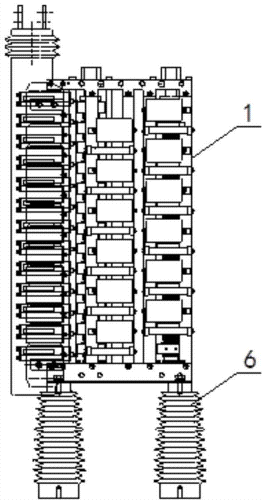
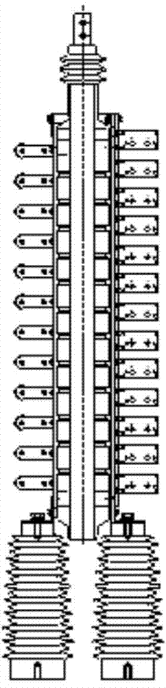
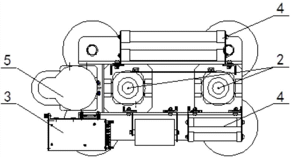
[0038] The specific implementation manners of the present invention will be further described in detail below in conjunction with the accompanying drawings.

[0039] This embodiment takes the modular thyristor valve group for solid-state composite switchgear as an example, such as Figure 1 to Figure 8 As shown, the modular thyristor valve group for solid-state composite switchgear provided by the embodiment of the present invention includes: modular thyristor valve group 1, thyristor valve string assembly 2, TCU board assembly 3, RC and voltage equalizing assembly 4, high frequency Energy sending component 5, epoxy cast insulator 6, thyristor 7, radiator 8, disc spring mechanism 9, upper flange 10, lower flange 11, epoxy pull belt 12, TCU board card 13, TCU board shielding box 14, Fixed plate 15, connecting terminal 16, voltage equalizing resistor 17, absorbing capacitor 18, supporting fixed plate 19, high frequency energy transmission CT20, fixing piece 21, primary side coil...


PUM


Abstract

The invention provides a modularized thyristor valve block for a solid combination switch device. The modularized thyristor valve block for the solid combination switch device comprises thyristor valve series assemblies, TCU board assemblies, resistance-capacitance voltage-sharing assemblies and high-frequency energy supply assemblies. The thyristor valve series assemblies are arranged between the resistance-capacitance voltage-sharing assemblies and connected with the resistance-capacitance voltage-sharing assemblies in parallel. The TCU board assemblies are connected with the high-frequency energy supply assemblies and then arranged at one side of the resistance-capacitance voltage-sharing assemblies. The TCU board assemblies respectively control the thyristor valve series assemblies and the resistance-capacitance voltage-sharing assemblies. Epoxy pouring insulators are arranged at the bottom of the modularized thyristor valve block. The modularized thyristor valve block for the solid combination switch device has the advantages that the thyristor valve block is of a vertical modularized structure and is in series connection in the 6kV to 35kV solid combination switch device in an independent or combined mode. Compared with the prior art, the modularized thyristor valve block for the solid combination switch device is capable of satisfying the requirement for voltage levels from 6kV to 35kV, good in universality, compact in structure, easy to install and capable of solving the problems occurring in the original structure mode due to the adoption of the integrated pouring type high-frequency energy supply CT.

Description

technical field [0001] The invention relates to a thyristor valve group, in particular to a modularized thyristor valve group used for a solid-state composite switching device. Background technique [0002] With the continuous development of the economy, power users have higher and higher requirements for power quality. Voltage deviation is an important aspect of power quality. At present, the distribution network system with wide coverage and large quantity has the status quo of large power supply radius and unreasonable structure, which causes the problem of voltage deviation to be more prominent. [0003] At present, the commonly used means of voltage adjustment are on-load voltage regulating transformer and switching capacitor bank. However, both the on-load tap changer and the switching capacitor bank have the disadvantage of not being able to operate frequently with the fluctuation of the load, resulting in excessive voltage deviation in some periods. When the mechan...

Claims


Application Information

Patent Timeline
Patent Type & Authority Applications(China)
IPC IPC(8): H03K17/56H01L25/07
Inventor 张雷常忠王承民袁洪亮郎平张伟华任西周
Owner STATE GRID CORP OF CHINA
Why Eureka
Try Eureka