
Power generation device and power generation method adopting salinity gradient power

A power generation device and the technology of salt difference energy, applied in the field of salt difference energy, can solve the problems that are not suitable for areas lacking fresh water resources, cannot adapt to the change of osmotic pressure along the process, and the efficiency of power generation system is low, so as to improve the membrane power density and effectively Contribute to commercialization and reduce the effect of pretreatment cost

Active Publication Date: 2014-03-05
HUAZHONG UNIV OF SCI & TECH
View PDF6 Cites 25 Cited by
  • Summary
  • Abstract
  • Description
  • Claims
  • Application Information

AI Technical Summary

Problems solved by technology

[0006] At present, salinity difference power generation often chooses the site where the river flows into the sea, and uses seawater and freshwater for infiltration. However, the limited concentration difference between seawater and freshwater results in low power density, and it is not suitable for areas where freshwater resources are scarce. Serious pollution increases the cost of pretreatment, making the traditional salinity difference power generation not applicable in my country
Moreover, the traditional single-backpressure single-stage pressure delay system has only one backpressure on the concentrated brine side, which cannot adapt to the change of osmotic pressure along the process, and the efficiency of the entire power generation system is very low

Method used


Image

  • Power generation device and power generation method adopting salinity gradient power

Examples


Embodiment Construction

[0032] In order to make the object, technical solution and advantages of the present invention clearer, the present invention will be further described in detail below in conjunction with the accompanying drawings. The description herein is only used to explain the present invention when referring to specific examples, and does not limit the present invention. In addition, the technical features involved in the various embodiments of the present invention described below may be combined with each other as long as they do not constitute a conflict with each other.

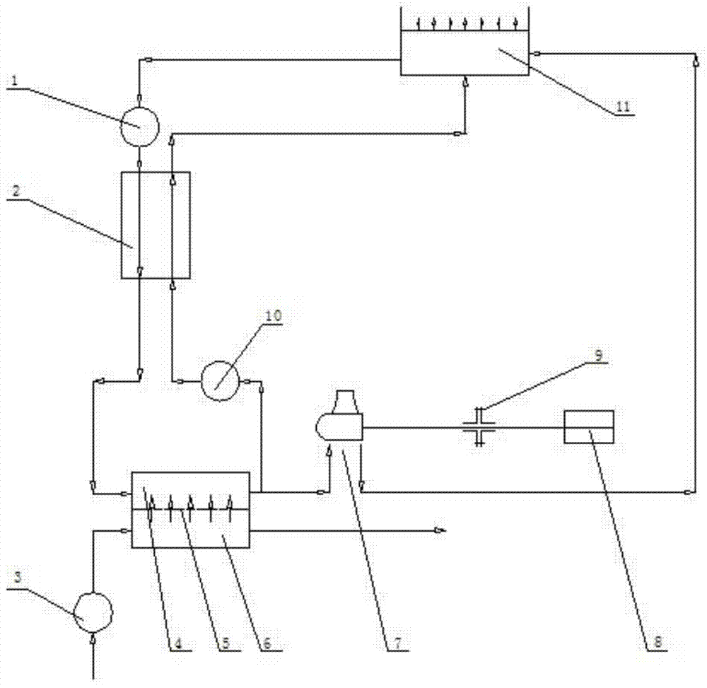
[0033] Such as figure 1 Shown is a schematic structural diagram of a salinity difference energy concentrated brine seawater power generation system according to an embodiment of the present invention. The arrows in the figure indicate the flow direction of the working fluid. The permeation device is a schematic diagram. It cannot be understood as a simple semi-permeable membrane dividing the container into two cham...


PUM


Abstract

The invention discloses a power generation device adopting salinity gradient power. The power generation device comprises a permeating device and water turbines. The permeating device comprises a permeating electrode formed by parallel connection of a plurality of permeable membrane elements and used for dividing strong salt water and seawater into a high-concentration side and a low-concentration side. The water turbines correspond to the high-concentration side of the permeating device and are connected with an engine through a coupler so as to drive a motor to operate. After the strong salt water and the seawater are fed into the high-concentration side and the low-concentration side of the permeating electrode, the permeating electrode can convert permeating pressure difference into hydrostatic pressure on the high-concentration side and exert back pressure in corresponding size by the aid of permeating electrode, and the water turbines can be driven to rotate to drive a generator to operate. The seawater is taken as a low-concentration water supply side and the seawater higher in concentration is used for permeating power generation, so that fresh water resources can be saved, pretreatment cost can be reduced, the permeating pressure difference can be increased, and power density can be increased; instability and difficult grid connection by the power generation mode are avoided due to the characteristics of easy storage of salt.

Description

technical field [0001] The invention belongs to the technical field of salt difference energy, and in particular relates to a salt difference energy generating device. Background technique [0002] Salinity difference energy refers to the chemical potential difference energy between seawater and freshwater or between two kinds of water with different salinity concentrations. It mainly exists in river estuaries and some inland saltwater lakes. It is a kind of marine energy with huge reserves. Osmosis is a phenomenon in which when two solutions of different concentrations are separated by a semipermeable membrane, the solvent (such as water) in the lower concentration solution automatically flows through the semipermeable membrane to the higher concentration solution until the chemical potential is balanced. Osmotic pressure is the additional pressure on the solution side to achieve osmotic equilibrium during osmosis. The driving force for osmosis comes from the chemical pote...

Claims


Application Information

Patent Timeline
Patent Type & Authority Applications(China)
IPC IPC(8): F03G7/00
CPCY02E10/30
Inventor 黄素逸舒良锁靳世平舒朝晖丁文武钱鑫蒋京楷刘奕琳梁宇明田中君谭凯王喜云梁鑫
Owner HUAZHONG UNIV OF SCI & TECH
Learn More