
Vulcanizing mold of rubber bushing

A technology of rubber bushing and vulcanization mold, applied in the field of molds, can solve the problems of insecure product size, inability to smoothly eject the mold, deformation of the lower cavity, etc., and achieve the effects of uniform force, simple structure, and reduced scrap rate.

Active Publication Date: 2014-03-05
NINGBO TUOPU GROUP CO LTD
View PDF4 Cites 14 Cited by
  • Summary
  • Abstract
  • Description
  • Claims
  • Application Information

AI Technical Summary

Problems solved by technology

Due to the large number of product cavities in the rubber bushing vulcanization mold, the ejector mechanism needs to eject all the bushing products at one time, and its ejection force is relatively large. When vulcanizing the bushing products with deep damping holes, the bushing The inner liner of the set product is thinner and longer than its outer liner and middle liner. Therefore, the shape of the lower mold cavity on the lower mold plate that accommodates the inner liner is also slender. When ejected The mechanism is only on the inner liner, and the rubber bush is subjected to excessive or uneven force, which is easy to deform in the lower cavity, which will lead to the following problems: 1. It is stuck in the lower cavity and cannot be ejected smoothly ; 2. The product size is not guaranteed, and the scrap rate is high

Method used


Image

  • Vulcanizing mold of rubber bushing
  • Vulcanizing mold of rubber bushing
  • Vulcanizing mold of rubber bushing

Examples


Embodiment

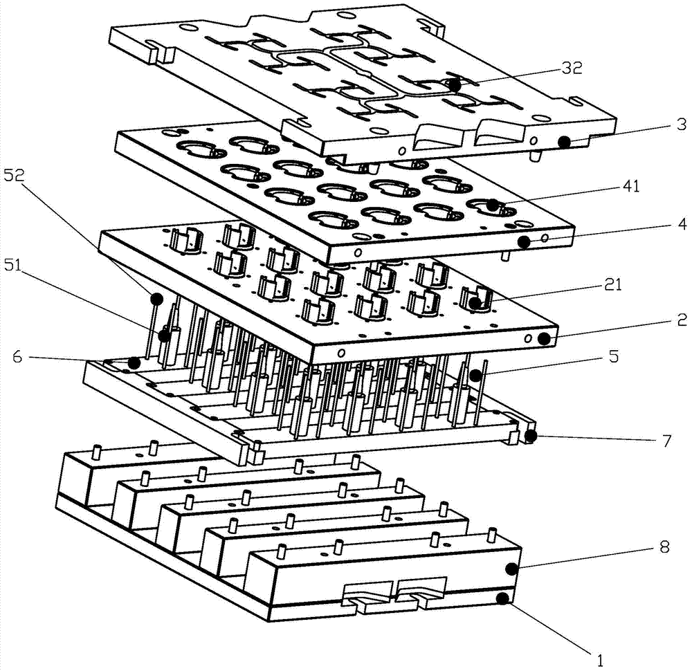
[0018] Embodiment: As shown in the figure, a rubber bush vulcanization mold includes a base plate 1, an ejection mechanism positioned on the base plate 1 that can move up and down, a lower template 2 located on the ejection mechanism and fixed on the base plate 1, and The upper template 3 above the template 2, the product positioning plate 4 between the lower template 2 and the upper template 3, the upper template 3 is provided with a plurality of upper mold cavities 31 and flow channels 32 communicated with the upper mold cavity 31, the lower template 2 is provided with a plurality of lower cavities 21, and the product positioning plate 4 is provided with a plurality of positioning cavities 41, and the upper cavity 31, the lower cavity 21 and the positioning cavity 41 are combined from top to bottom to form accommodating rubber bushes and For a fixed product cavity, the ejector mechanism includes a plurality of ejector pin groups 5, and the ejector pin group 5 includes a first...


PUM


Abstract

The invention discloses a vulcanizing mold of a rubber bushing. The vulcanizing mold comprises a bottom plate, an ejecting mechanism, a lower mold plate, an upper mold plate and a product positioning plate, wherein the ejecting mechanism is arranged on the bottom plate and can move up and down; the lower mold plate is arranged on the ejecting mechanism and is fixed on the bottom plate; the upper mold plate is arranged above the lower mold plate; the product positioning plate is arranged between the lower mold plate and the upper mold plate; the upper mold plate is provided with a plurality of upper cavities and flowing channels communicated with the upper cavities; the lower mold plate is provided with a plurality of lower cavities; the product positioning plate is provided with a plurality of positioning cavities; the ejecting mechanism comprises a plurality of ejecting rod groups; each ejecting rod group comprises a first ejecting rod and a plurality of second ejecting rods which are arranged around the first ejecting rod in a circle; the lower mold plate is provided with a plurality of ejecting hole groups; each ejecting hole group is distributed around one lower cavity along one circle. The vulcanizing mold disclosed by the invention has the advantages that when in demolding, the ejecting mechanism supports an inner-layer lining pipe and an outer-layer lining pipe simultaneously, the stressing of all the parts of the rubber bushing is uniform, and the deformation is unlikely to occur, so that the locking of a product can be prevented, smooth demolding of the product can be guaranteed, the size of the product can be guaranteed, and the rejection rate is reduced.

Description

technical field [0001] The invention relates to a mold, in particular to a rubber bush vulcanization mold. Background technique [0002] A large number of flexible connections such as rubber bushings are used in modern automobile suspensions to meet the needs of vehicle vibration and noise reduction. At present, a commonly used rubber bushing includes three layers of liner, which are outer liner, middle liner and inner liner. The manufacturing process is to put the multi-layer liner into the rubber bushing vulcanization mold In the mold cavity, the multi-layer liner is vulcanized and connected together through the vulcanization process. [0003] Existing vulcanization molds for rubber bushes generally include a base plate, an ejection mechanism located on the base plate, a lower template located on the ejector mechanism and fixed on the base plate, and a detachable connection between the lower template and the lower template. The upper template, the product positioning pla...

Claims


Application Information

Patent Timeline
IPC IPC(8): B29C33/44B29C35/00
Inventor 郑鹏军韦雪雯朱宝龙
Owner NINGBO TUOPU GROUP CO LTD
Learn More