
A pipeline inner wall spraying device

A spraying device and pipeline technology, which is applied to the device and coating of the surface coating liquid, can solve the problems such as the influence of the spraying length, the trolley cannot walk freely, etc., and achieve the effect of convenient use

Active Publication Date: 2016-11-09
YANTAI XINHAI MINING MACHINERY
View PDF7 Cites 0 Cited by
  • Summary
  • Abstract
  • Description
  • Claims
  • Application Information

AI Technical Summary

Problems solved by technology

Also, Chinese patent 201110202843.6 proposes a pipe diameter self-adaptive inner wall spraying equipment for large-diameter steel pipes. These two spraying devices are all provided with a device similar to a guide rail to provide a walking track for the trolley, so that the trolley cannot walk freely. The length of the spray will be affected by the track

Method used


Image

  • A pipeline inner wall spraying device
  • A pipeline inner wall spraying device
  • A pipeline inner wall spraying device

Examples


no. 1 example

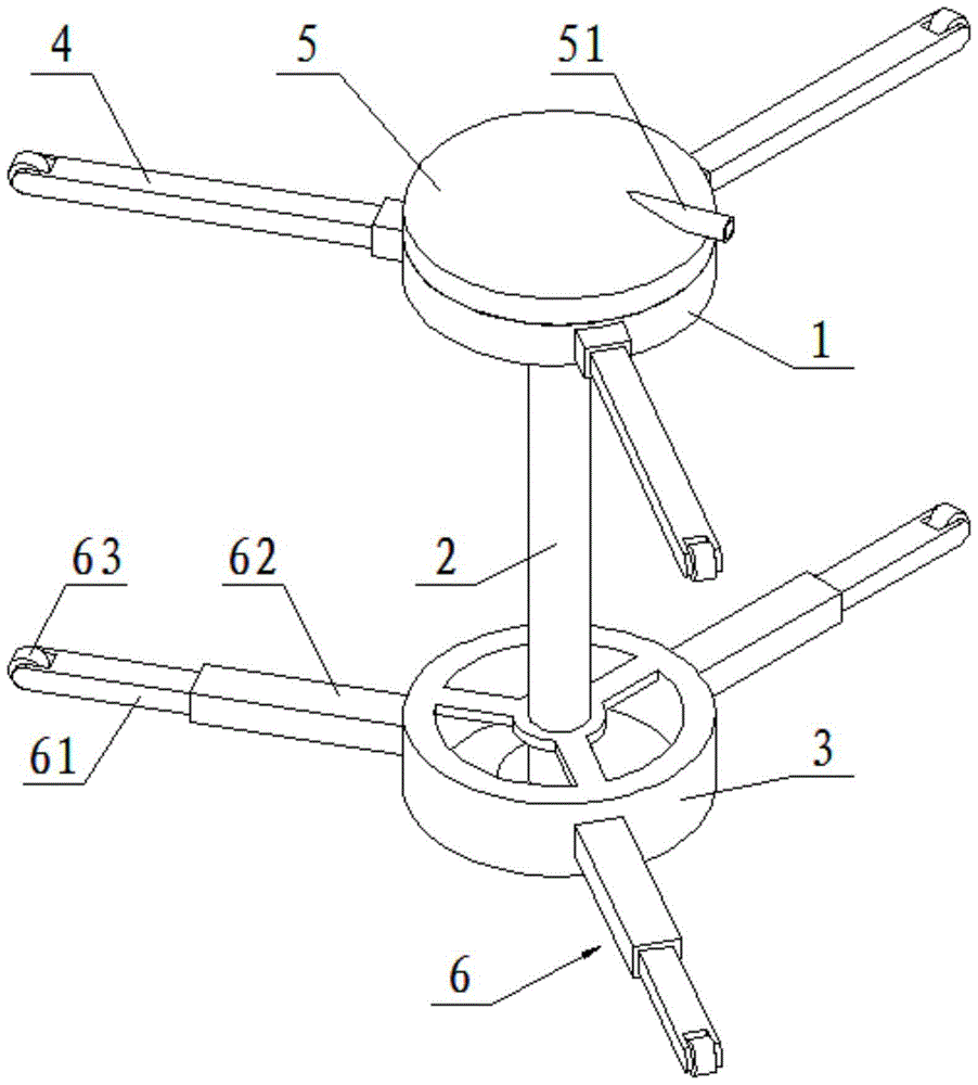
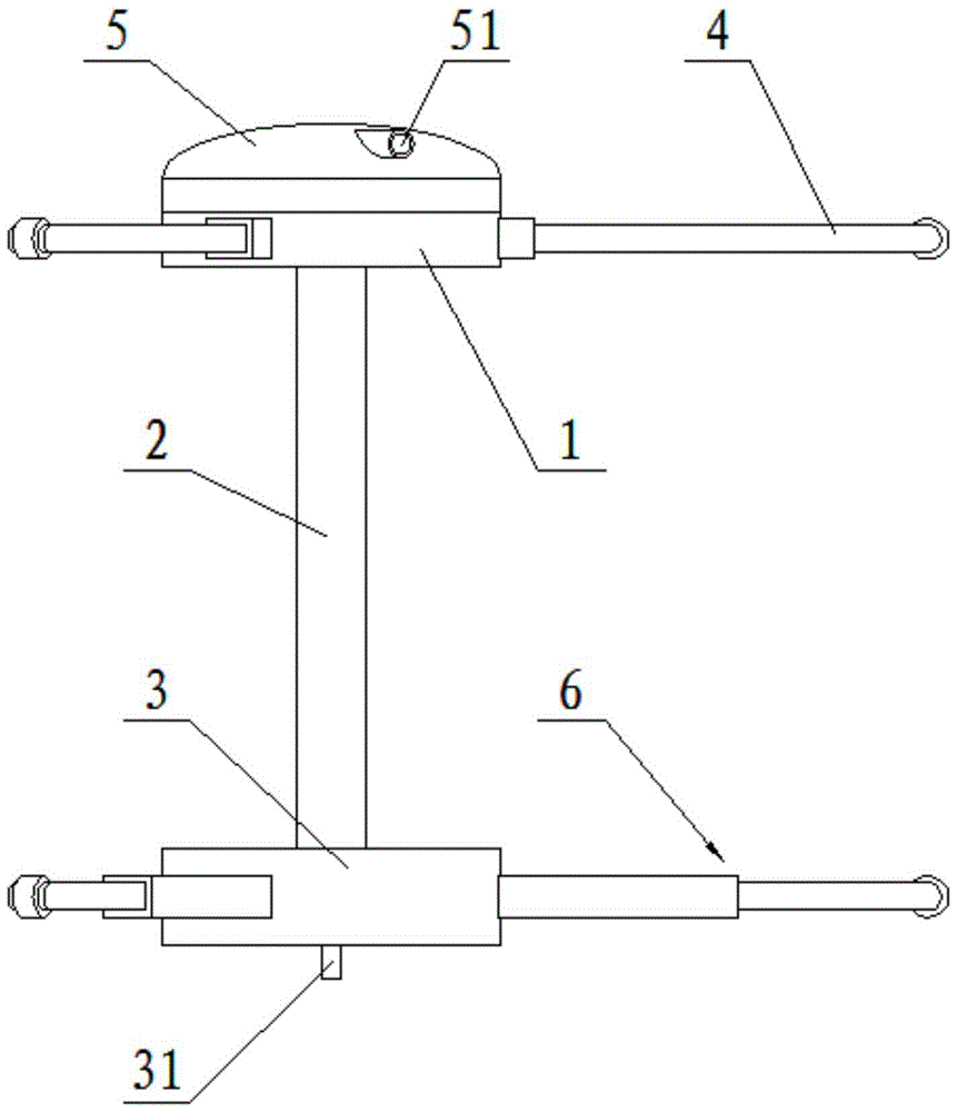
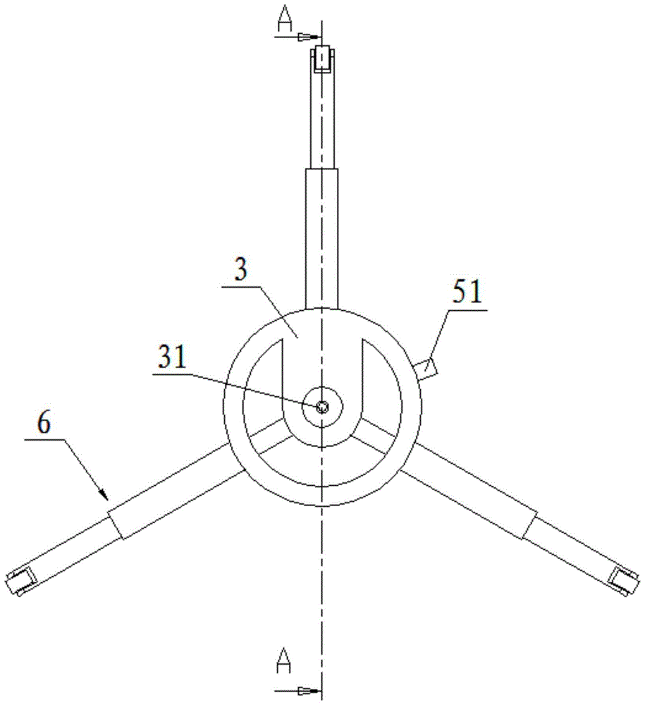
[0025] figure 1 , figure 2 , image 3 , Figure 4 As shown, a pipeline inner wall spraying device includes a front stator 1, a rear stator 3, and a strut 2; one end of the strut 2 is fixedly connected to one end of the front stator 1, and the other end of the strut 2 is connected to the One end of the rear stator 3 is fixedly connected; the other end of the front stator 1 is provided with a nozzle 5 , and at least three groups of first legs 4 are evenly distributed on the circumferential surface of the front stator 1 . The inside of 1 is provided with a first motor 11 that drives the nozzle 5 to rotate; the other end of the rear stator 3 is provided with a nozzle adapter 31, and the circumferential surface of the rear stator 3 is evenly distributed with at least three groups of second Outrigger 6, the interior of the rear stator 3 is provided with a battery 7, the battery 7 is each drive motor (the drive motor can be the first motor 11, the second motor 64, the third motor...

no. 2 example

[0030] like Figure 5 As shown, the structure of the first leg 4 in this embodiment is different from the structure of the first leg 4 in the first embodiment, and the structure of the first leg 4 in this embodiment is different from that of the second leg in the first embodiment. The structure of the legs 6 is the same, and other conditions are the same as those of the first embodiment.


PUM


Abstract

The invention relates to a pipeline inner wall spraying device, comprising a front stator, a rear stator, and a pillar; one end of the pillar is fixedly connected to one end of the front stator, and the other end of the pillar is connected to the rear stator. One end is fixedly connected; the other end of the front stator is provided with a spray head, and at least three sets of first legs are evenly distributed on the circumferential surface of the front stator, and the inside of the front stator is provided with a first A motor; the other end of the rear stator is provided with a nozzle adapter, and at least three groups of second legs are evenly distributed on the circumferential surface of the rear stator; the nozzle and the nozzle adapter are connected through a conduit connected; the end of the second leg is provided with a roller and a second motor driving the roller. At least three front stators and rear stators with drive rollers are evenly distributed at both ends of the pillar respectively, so that the spraying device can travel more flexibly.

Description

technical field [0001] The invention relates to a spraying device, in particular to a spraying device for the inner wall of a pipeline. Background technique [0002] Sandblasting and gluing is a common method for industrial surface treatment. In the past, sandblasting and gluing in rectangular pipes or circular pipes used to be manually entered, manually operated, or operated by feeling from the outside, and the internal working conditions could not be observed, which was prone to leakage Overcoat, overcoat. [0003] The existing Chinese patent 200820033683.0 proposes a large-diameter gas transmission steel pipe inner coating spraying equipment, which mainly includes a V-shaped support frame, a trolley, a trolley driving and traveling device, and a spraying device. Among them, the spraying device includes a nozzle, a telescopic frame, a paint pump and a paint storage tank. Install the nozzle on the telescopic frame, and adjust the position of the nozzle by adjusting the po...

Claims


Application Information

Patent Timeline
Patent Type & Authority Patents(China)
IPC IPC(8): B05C7/02B05C11/00
Inventor 王有春丁辉张云龙荆永卿刘宁
Owner YANTAI XINHAI MINING MACHINERY
Learn More