Autofocus camera system and control method thereof

A technology of automatic focusing and control method, which is applied to closed-circuit television systems, components of television systems, cameras, etc., can solve the problems of complex structure and control, unable to form focusing, verification and correction, etc., to improve driving efficiency and control efficiency. Effect

Inactive Publication Date: 2014-02-26
HDC AG
View PDF4 Cites 6 Cited by
  • Summary
  • Abstract
  • Description
  • Claims
  • Application Information

AI Technical Summary

Problems solved by technology

[0010] However, since this type of structure will increase the volume of the closed-circuit television camera, so that there are many disadvantages and limitations in manufacturing, setting, etc., there have been charge-coupled device cameras that generally have a size of 1 / 4 inch and are capable of autofocus (of course, In the case of a car camera, a 1 / 3-inch charge-coupled device is also used)
[0011] However, in order to reduce the size of the charge-coupled device camera, a single motor is used to process the autofocus and zoom functions at the same time, so the structure and control are complicated, and the focus cannot be achieved at a specific zoom ratio, and the processing time is long.
That is, in the case of using a single motor, it is necessary to manually adjust the zoom and focus range adjustments, so there are problems in that the design of the camera is difficult and complicated, the control is also difficult, and the processing time is increased.
[0012] Not only that, the signal processing method embodied in the previous closed-circuit television needs to form the conversion between analog signal and digital signal at any time through a channel, so when the user interface and video signal processing are performed, the load will be increased, and the storage capacity will increase. increase, there are difficulties in the control of efficiency
[0013] In addition, since the conventional closed-circuit television does not have the function of verifying and correcting the errors that occur during the automatic focusing of the charge-coupled device camera, there is a limit that cannot be dealt with when errors occur.

Method used


Image

  • Autofocus camera system and control method thereof
  • Autofocus camera system and control method thereof
  • Autofocus camera system and control method thereof

Examples


Embodiment Construction

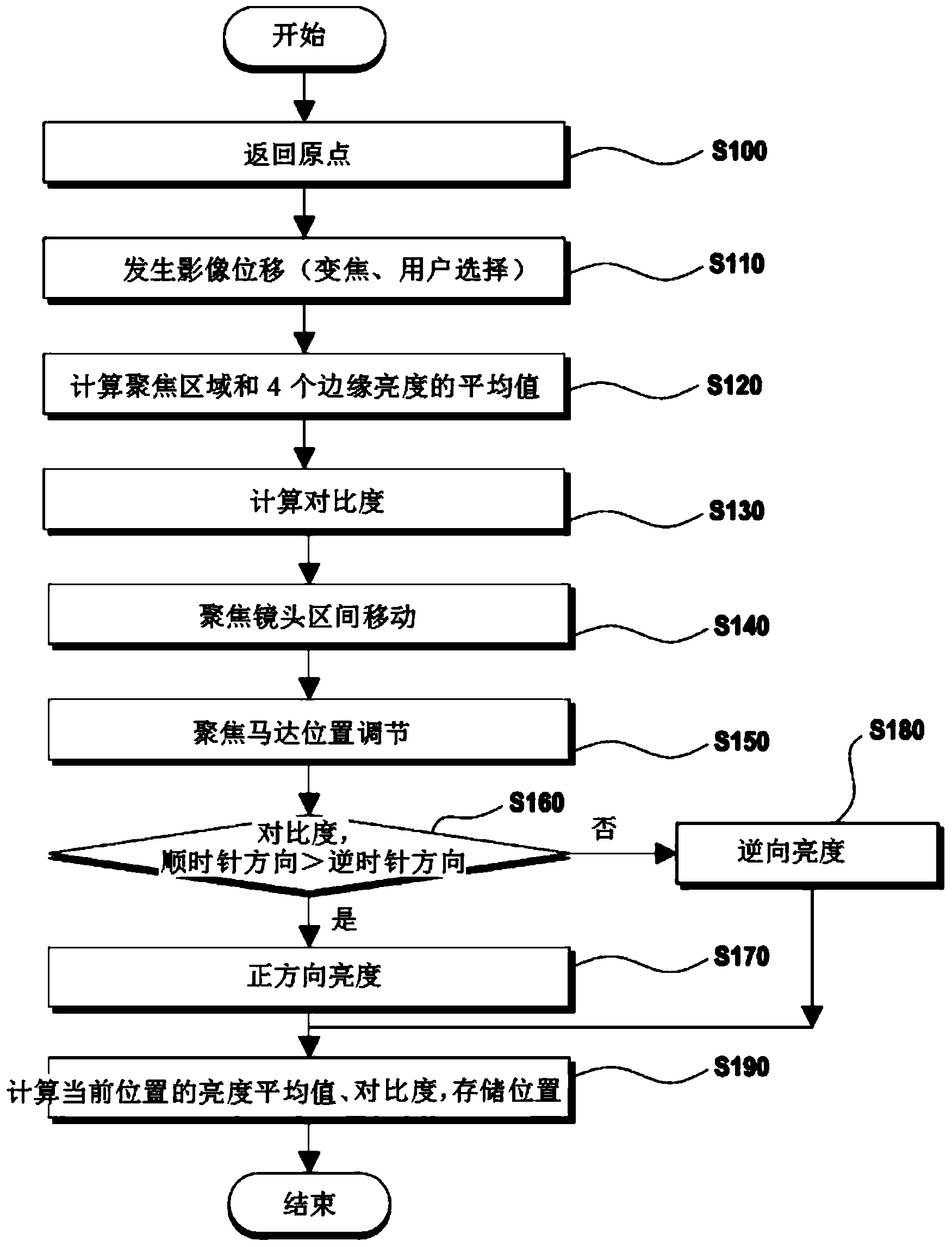
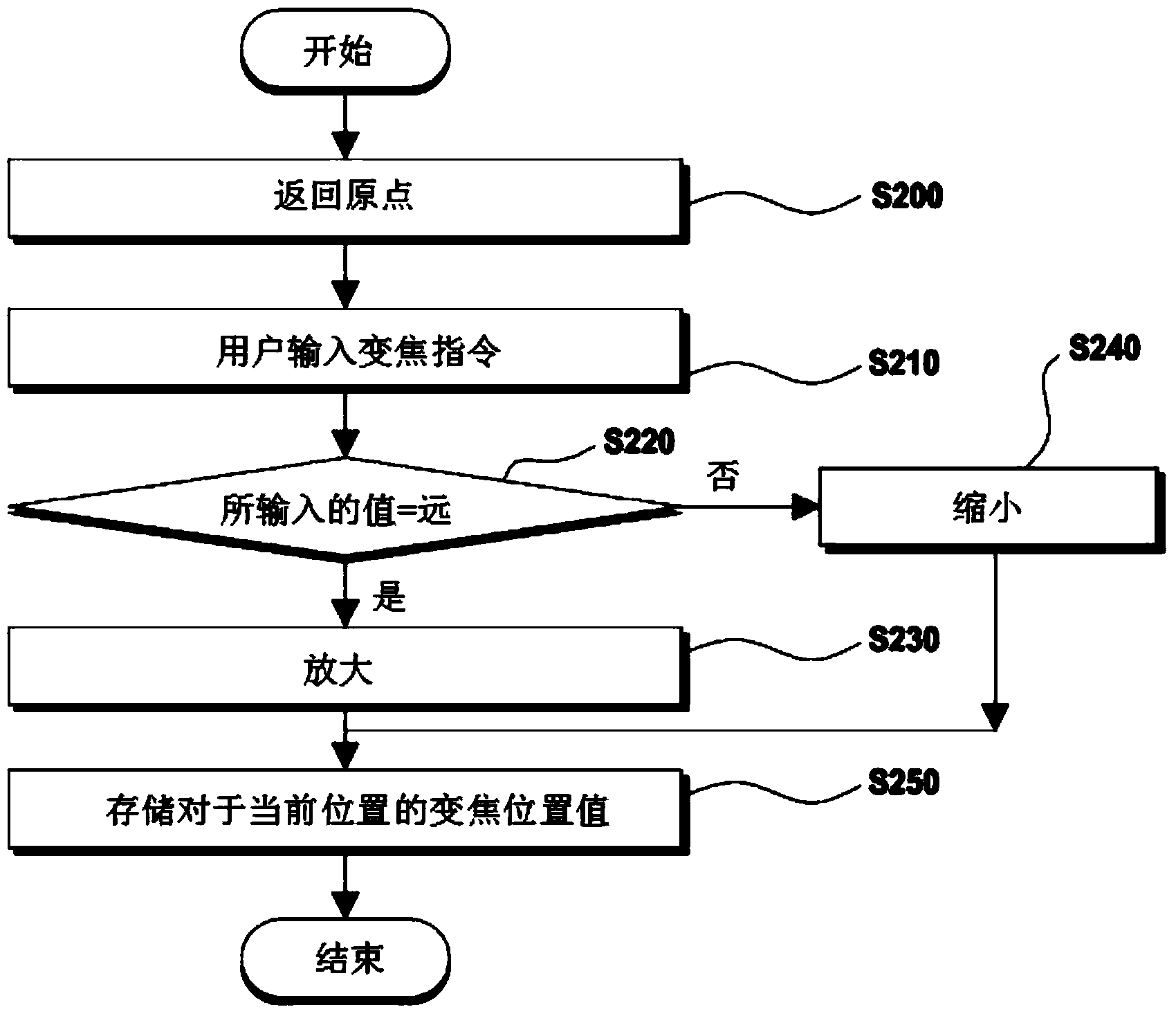
[0028] Hereinafter, preferred embodiments of the present invention will be described in more detail with reference to the accompanying drawings.

[0029] figure 1 It is an exemplary structural block diagram of the autofocus camera system of the present invention.

[0030] Such as figure 1 As shown, the autofocus camera system of the present invention includes a main processor 100 .

[0031]The above-mentioned main processor 100 is executed in a closed-circuit television and is necessary for implementing autofocus and zoom-in / zoom-out, focus error interpretation and correction, RS-485 communication, and modulation transfer function (MTF, Modulation Transfer function) related to the present invention. The overall control of the chipset.

[0032] Moreover, the above-mentioned main processor 100 links the storage unit 200, and the above-mentioned storage unit 200, as a memory device, has an Electrically Erasable Programmable Read-Only Memory (EEPROM, Electrically Erasable Progr...


PUM


Abstract

The present invention relates to an autofocus camera system and a control method thereof, and relates to a CCTV camera system which comprises a main processor installed in a CCTV, a memory unit connected with the main processor, an input unit, a CCD camera, a video processing unit, a focus lens, and a zoom lens, wherein: the system is designed to input and output control instructions through RS-485 communication; the system is controlled by a focus motor driver and a zoom motor driver which are connected to the main processor in which a focus motor and a zoom motor are comprised of stepping motors; and the focus motor driver performs auto-focusing using a luminance and a contrast ratio displayed in an image of a corresponding point after performing a step movement to a focus point divided into sections of multiple steps according to the size of a lens, thereby implementing an autofocus through a 1 / 3" CCD at the CCTV camera, and controlling the drive of the zoom and autofocus through each of the stepping motors to enable high-speed driving, increase the driving efficiency and control efficiency, and enable self-verification and correction for an error in the autofocus.

Description

technical field [0001] The present invention relates to an auto-focus camera system and its control method, and in more detail, relates to a separation of focus function and zoom function, so that it can be driven by a separate drive source, but also enables a charge-coupled device of 1 / 3" size (CCD, Charge-Coupled Device) enables autofocus and zoom functions to be performed in closed-circuit television by directly driving and controlling a stepping motor, thereby shortening start-up time, improving efficiency, and including automatic correction functions. Focus camera system and control method thereof. Background technique [0002] As stated in the gist, CCTV (Closed Circuit Television) is installed and used in various fields such as monitoring / management of vulnerable areas or places where people frequently come and go, industrial equipment, etc., vehicles, and subway electric vehicles. [0003] Recently, not only in department stores, banks, exhibition halls, etc., but a...

Claims


Application Information

Patent Timeline
Patent Type & Authority Applications(China)
IPC IPC(8): H04N7/18H04N5/225G03B13/36G02B7/09
CPCH04N5/23296H04N7/183H04N5/23212H04N23/673H04N23/69H04N25/615H04N7/18G03B13/36G02B7/09H04N23/00
Inventor 丁盛虎
Owner HDC AG
Why Eureka
Try Eureka