In-line back pressure fluid regulator

A back pressure regulator, fluid regulator technology, applied in fluid pressure control, control/regulation system, fluid pressure control without auxiliary power, etc., can solve problems such as small pipes

Active Publication Date: 2014-02-26
TESCOM CORP
View PDF9 Cites 6 Cited by
  • Summary
  • Abstract
  • Description
  • Claims
  • Application Information

AI Technical Summary

Problems solved by technology

The pipe is too small to receive a conventional back pressure regulator coupled to an agent injection line provided in the pipe

Method used


Image

  • In-line back pressure fluid regulator
  • In-line back pressure fluid regulator
  • In-line back pressure fluid regulator

Examples


Embodiment Construction

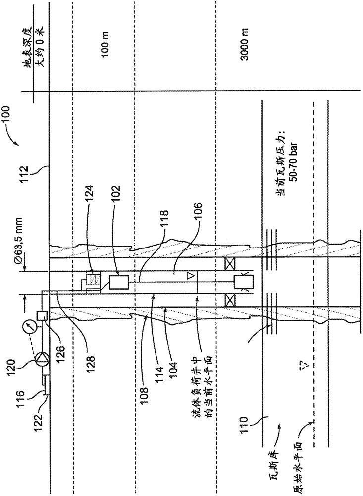
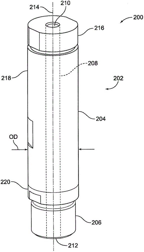
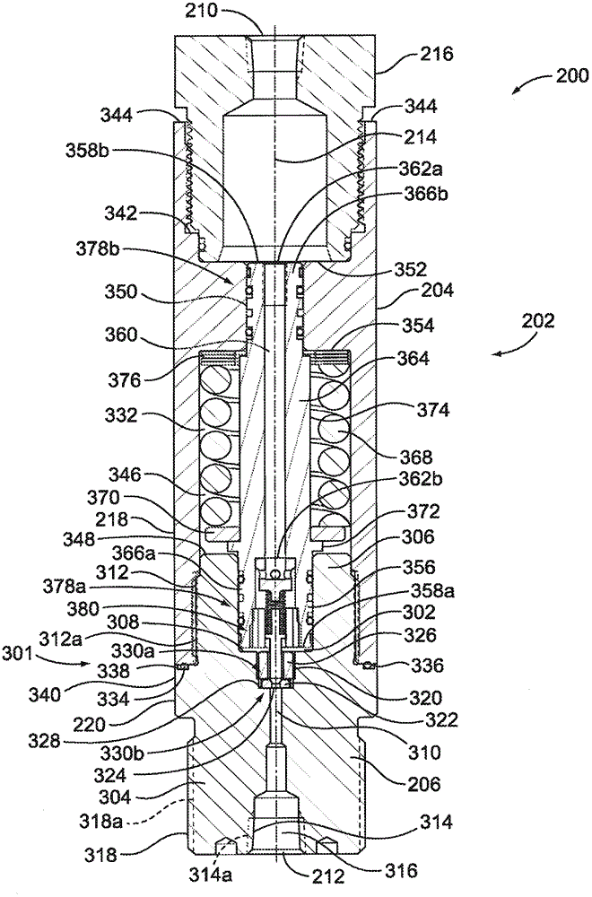
[0016] The coaxial backpressure fluid regulators described herein have a housing that defines a substantially straight or linear fluid flow path between an inlet and an outlet. More specifically, exemplary backpressure fluid regulators may be coaxially coupled with respect to a flow path of a process fluid system. For example, the inlet, outlet, flow control element, loading chamber, and sensing chamber of the exemplary fluid regulators described herein are coaxially aligned to define a substantially straight or linear fluid flow path for the backpressure fluid regulator. As a result, the example backpressure fluid regulators described herein provide a substantially smaller or reduced envelope or footprint compared to conventional backpressure fluid regulators. Accordingly, the example backpressure fluid regulators described herein may be advantageously used in applications with relatively small or severe space constraints (eg, exploratory well applications). Additionally, th...


PUM


Abstract

In-line back pressure fluid regulators are described. An example in-line fluid regulator includes a regulator body defining a sensing chamber and an outlet of a fluid flow path of the fluid regulator. The outlet is in fluid communication with the sensing chamber via a first flow passageway in the regulator body. A bonnet is coupled to the regulator body and defines an inlet of the fluid flow path and a loading chamber disposed between the sensing chamber and the inlet. The loading chamber is substantially sealed relative to the fluid flow path of the fluid regulator. A pressure sensor is disposed between the inlet and the sensing chamber, where the pressure sensor defines a second flow passageway to fluidly couple the inlet and the sensing chamber.

Description

technical field [0001] The disclosure herein relates generally to fluid regulators, and more specifically to coaxial backpressure fluid regulators. Background technique [0002] Process control systems often employ pressure regulators (eg, back pressure regulators) to control or maintain the pressure of process fluids to protect instruments or other control equipment that are sensitive to high pressures. Fluid regulators, such as back pressure regulators, typically include a fluid valve assembly with a pressure sensor, such as a piston, to sense the pressure of the pressurized fluid at the inlet of the regulator. When the pressure of the pressurized fluid at the inlet exceeds a reference or set pressure (such as provided by the fluid regulator), the pressure sensor causes the flow control element of the fluid valve to open to allow fluid to flow through the regulator body between the inlet and outlet , wherein the regulator body can be coupled to a low pressure system utili...

Claims


Application Information

Patent Timeline
Patent Type & Authority Applications(China)
IPC IPC(8): G05D16/10E21B21/10F16K17/04
CPCG05D16/103E21B47/06E21B34/10G05D16/024Y10T137/7854Y10T137/7922Y10T137/7835G05D16/10
Inventor M·K·奥尔布里施R·尼贝尔F·拉普施
Owner TESCOM CORP
Why Eureka
Try Eureka