Vented high pressure valve

A valve chamber and valve body technology, which is applied in the field of high-pressure valves, can solve the problems of valve motion control, valve body and valve seat wear, etc.

Inactive Publication Date: 2017-02-15
CATERPILLAR INC
View PDF10 Cites 3 Cited by
  • Summary
  • Abstract
  • Description
  • Claims
  • Application Information

AI Technical Summary

Problems solved by technology

Although the injection line of the '785 patent vents, this venting does not address valve motion control and minimize wear between the valve body and seat

Method used


Image

  • Vented high pressure valve
  • Vented high pressure valve
  • Vented high pressure valve

Examples


Embodiment Construction

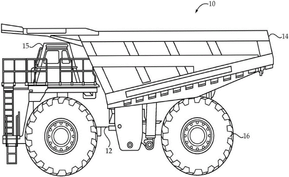
[0019] Referring now to the accompanying drawings, and specifically to figure 1 , the machine 10 includes a machine body 12 supported on a vehicle 16 . In the illustrated embodiment, machine 10 is shown as a mining truck and vehicle 16 is shown as wheels. However, the machine 10 may take a very wide variety of forms, and the form of the vehicle 16 may vary widely. For example, the vehicle 16 could be a track or possibly even a propeller if the machine is in the form of a sea-going vessel. Machine 10 includes a dump body 14 pivotally attached to machine body 12 and also includes an operator station 15 . It is contemplated that the duty cycle of the machine 10 includes periods of idling and not moving, such as when the machine 10 is waiting to accommodate a load, such as ore, into the dump body 14, to dump a load, and possibly even to be refueled. Between these quiescent idle periods, it is contemplated that the machine 10 operating at full power with a heavy load in the dump...


PUM


Abstract

A valve assembly for a fuel pump is disclosed. In certain aspect, the valve assembly includes a housing defining a valve chamber, a valve inlet in fluid communication with the valve chamber, a valve outlet in fluid communication with the valve chamber, a valve seat; a valve body movably disposed within the valve chamber, a retainer sealingly engaging the housing and defining a cavity between the base portion of the valve body and the retainer, wherein the retainer comprises one or more control orifices formed therein and configured to provide fluid communication to the cavity to regulate a position of the valve body based on at least a pressure difference between the valve chamber and the cavity, and a spring member disposed between the retainer and the valve body, wherein the spring member is configured to bias the valve body.

Description

technical field [0001] The patented invention relates generally to high pressure valves, and more particularly to a system and method for venting high pressure valves. Background technique [0002] High pressure fuel pump systems are used in a variety of motorized platforms, including those of trucks, buses, and automobiles, as well as off-highway machines used in the construction, mining, and agricultural fields. They are also used in marine and industrial applications including, for example, power generation and oil drilling equipment. These pumps are usually driven mechanically via the associated engine for delivering fuel at high pressure to the fuel injectors and into the individual cylinders of the engine through a so-called common rail fuel system. [0003] Common rail fuel systems typically include fuel delivery components associated with high pressure variable delivery pumps. A variable delivery pump can efficiently deliver high pressure fuel into a manifold that ...

Claims


Application Information

Patent Timeline
Patent Type & Authority Applications(China)
IPC IPC(8): F16K1/32F16K1/34
CPCF16K1/32F16K1/34F02M63/0295F02M59/462F16K15/026F16K15/025F16K27/0209F02M63/023F16K24/04
Inventor D·马克A·R·斯托克纳J·尤内斯
Owner CATERPILLAR INC
Why Eureka
Try Eureka