
Hydraulic pendulum force measuring mechanism

A technology of force measurement and hydraulic pressure, which is applied in the direction of measuring devices, measurement of force balance force, instruments, etc., can solve problems such as low precision, changes in indication values, inability to meet high-precision detection requirements, and long-term use. Achieve the effect of improving sliding performance and ingenious structure

Active Publication Date: 2015-09-02
WUXI JIANYI INSTR & MACHINERY
View PDF4 Cites 0 Cited by
  • Summary
  • Abstract
  • Description
  • Claims
  • Application Information

AI Technical Summary

Problems solved by technology

[0002] In the existing domestic mechanical force measurement technology, hydraulic pressure testing machines for testing the compressive strength of cement test blocks use hydraulic springs to measure force. Due to spring fatigue, changes in the elasticity of the spring will cause changes in the indication value, resulting in The measurement data is inaccurate, and the accuracy is not high, generally within ±2%, which cannot meet the high-precision detection requirements and long-term use, and the maximum force of the experiment is limited

Method used


Image

  • Hydraulic pendulum force measuring mechanism
  • Hydraulic pendulum force measuring mechanism

Examples


Embodiment Construction

[0016] The present invention will be further described below in conjunction with specific drawings and embodiments.

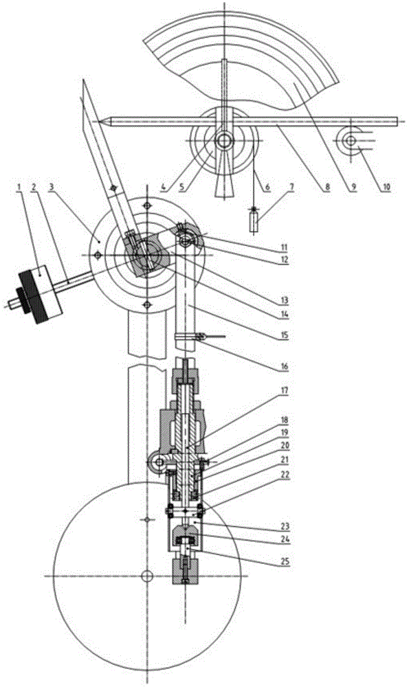
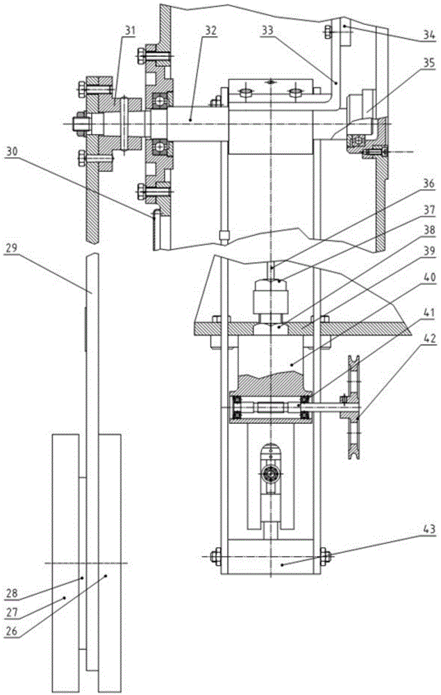
[0017] Such as figure 1 , figure 2 As shown, including balance thallium 1, balance rod 2, rear bearing flange seat 3, pointer 4, worm gear 5, string 6, weight 7, worm 8, dial 9, support wheel 10, bearing 11, connecting rod shaft 12. Swing rod shaft seat 13, conical pin 14, pull plate 15, limit bumper 16, force measuring rod 17, gear 18, force measuring sleeve 19, shaft sleeve 20, joint cap 21, transverse shaft 22, casing 23 , top block 24, bearing shaft 25, first pendulum 26, second pendulum 27, third pendulum 28, pendulum 29, upper box cover 30, pendulum flange seat 31, pendulum shaft 32, bent plate 33. Push plate 34, front bearing flange seat 35, oil pipe 36, first nut 37, second nut 38, upper box body 39, force measuring bush seat 40, screw rod 41, pulley 42, connecting rod shaft seat 43 etc.

[0018] Such as figure 1 , figure 2 As shown, a hydraulic...


PUM


Abstract

The invention belongs to the technical field of a measuring device and relates to a hydraulic pendulum bob force measuring mechanism used for detecting pressure strength of a cement test block. The force measuring mechanism comprises an upper box body, wherein a pendulum rod shaft is rotatably arranged on the upper box body, a front end of the pendulum rod shaft penetrates through an outer side of the upper box body, a shaft diameter is fixed with a pendulum rod flange seat, a pendulum rod is fixed on the pendulum rod flange seat through a fastening bolt, the pendulum rod shaft is arranged on a shaft in the upper box body and is fixedly connected with a pendulum rod shaft seat through a taper bolt, two ends of a connection rod shaft are rotatably arranged on the pendulum rod shaft seat through a bearing respectively, two ends of an outer side of the connection rod shaft corresponding to the pendulum rod shaft seat are respectively provided with a pull board, each pull board is respectively arranged along a length direction of the upper box body and penetrates through the outer side of the upper box body, and end portions of the pull boards which penetrate through the outer side of the upper box body are fixed with the pendulum rod shaft seat. Through the force measuring mechanism, a largest force is enabled to change according to weight change of a pendulum bob, the force measuring mechanism is converted to a load indication mechanism through calculation to acquire a measurement result, and an upper limit of measurement can reach above kilotons.

Description

technical field [0001] The invention belongs to the technical field of measuring devices, and relates to a hydraulic pendulum force-measuring mechanism for testing the pressure strength of a cement test block. Background technique [0002] In the existing domestic mechanical force measurement technology, the hydraulic pressure testing machine for testing the compressive strength of the cement test block adopts the hydraulic spring force measurement. The spring force measurement mechanism is due to the fatigue of the spring, and the change of the elasticity of the spring will cause the change of the indication value, resulting in The measurement data is inaccurate, and the accuracy is not high, generally within ±2%, which cannot meet the high-precision detection requirements and long-term use, and the maximum force of the experiment is limited. Contents of the invention [0003] The purpose of the present invention is to overcome the deficiencies in the prior art and provid...

Claims


Application Information

Patent Timeline
Patent Type & Authority Patents(China)
IPC IPC(8): G01L1/08G01N3/06
Inventor 沈怡辰陈筠孟建平
Owner WUXI JIANYI INSTR & MACHINERY
Learn More