
Relative-position detection method of band-like material

A detection method and relative position technology, applied in the direction of measuring devices, electrical devices, instruments, etc., can solve the problems of low transparency, dust interference, etc., and achieve the effect of simple detection structure

Inactive Publication Date: 2014-02-26
北京金自能源科技发展有限公司
View PDF3 Cites 11 Cited by
  • Summary
  • Abstract
  • Description
  • Claims
  • Application Information

AI Technical Summary

Problems solved by technology

Among them, the inductive detection method can only detect magnetic materials, and the photoelectric detection method can only detect materials with low transparency, and is seriously interfered by ambient light, dust and other pollution.

Method used


Image

  • Relative-position detection method of band-like material
  • Relative-position detection method of band-like material
  • Relative-position detection method of band-like material

Examples


Embodiment Construction

[0015] The present invention will be further described in detail with reference to the accompanying drawings and embodiments.

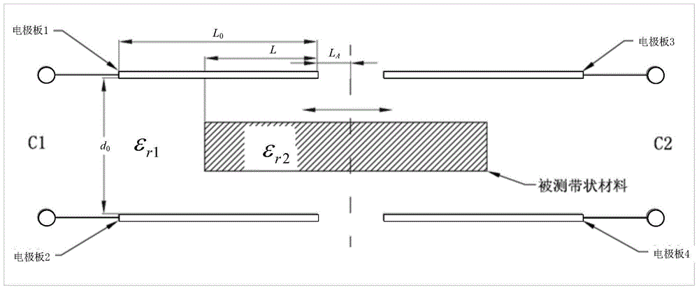
[0016] Combine below figure 1 The method of detecting the relative position of the strip-shaped material according to the present invention will be described.

[0017] Step 1: Arrange the detection structure.

[0018] The detection mechanism consists of four parallel electrode plates of the same size and shape, such as figure 1 shown. The electrode plate 1 and the electrode plate 2 form a capacitor C1, and the electrode plate 3 and the electrode plate 4 form a capacitor C2. The capacitors C1 and C2 are respectively arranged on the left and right sides of the production line of the strip material to be tested. In the embodiment of the present invention, preferably, the two capacitors are left-right symmetrical about the vertical plane where the centerline of the production line of the strip-shaped material to be tested is located. The strip materi...


PUM


Abstract

The invention provides a relative-position detection method of a band-like material. The relative-position detection method is used for detecting the relative position and the width of the band-like material on a production line. According to the relative-position detection method, four electrode plates having the same size and shape are taken, every two electrode plates constitute a capacitor, the two capacitors are distributed on the left side and the right side of the production line of the tested band-like material, and the tested band-like material passes through the space between the upper two electrode plates and the lower two electrode plates of the two capacitors; the capacitance variable quantity of the capacitors is measured under the situations that the tested band-like material is not inserted and the tested band-like material is inserted, the lengths of the parts, inserted in the capacitors, of the tested band-like material are determined according to the tested band-like material, the width of the tested band-like material is determined according to geometrical distances, and deviation of the tested band-like material is determined according to the geometrical distances. The relative-position detection method is free of limitation of tested materials and environmental disturbance; when the widths of the tested materials are known and the capacitor on one side breaks down, single-side operation can be conducted.

Description

technical field [0001] The invention belongs to the technical field of measuring the relative position and width of strip materials, and specifically realizes the detection of the relative position and width through a capacitance measuring method. Background technique [0002] In the production of strip materials, the finished materials need to be wound into coils, or the strip materials need to be uncoiled and then processed. In the process of uncoiling or coiling, the center position of the material needs to be kept at the center of the production line or a certain reference line. Strip materials involve a wide variety, such as plastic film, paper, steel, aluminum, copper, etc. It can be divided into metal or non-metal, magnetic material or non-magnetic material. In the prior art, several detection methods such as inductive type and photoelectric type are used to realize positioning. Among them, the inductive detection method can only detect magnetic materials, and the ...

Claims


Application Information

Patent Timeline
Patent Type & Authority Applications(China)
IPC IPC(8): G01B7/00G01B7/02
Inventor 陈小磊王勇刘松斌高健张屹李峰凯王敏肖铁妹穆慧灵
Owner 北京金自能源科技发展有限公司
Learn More