Locking device

A locking device and lock nut technology, which is applied in the direction of locking fasteners, turbine/propulsion device lubrication, threaded fasteners, etc., can solve problems such as low reliability and easy failure of locking effect, and achieve The effect of improving reliability

Active Publication Date: 2014-02-26
CHINA HANGFA SOUTH IND CO LTD
View PDF7 Cites 6 Cited by
  • Summary
  • Abstract
  • Description
  • Claims
  • Application Information

AI Technical Summary

Problems solved by technology

[0003] The purpose of the present invention is to provide a locking device to solve the technical problems in the prior art that the lock plate and other parts use the property of material deformation to achieve locking, and the locking effect is easy to fail and the reliability is not high.

Method used


Image

  • Locking device
  • Locking device
  • Locking device

Examples


Embodiment Construction

[0023] The embodiments of the present invention will be described in detail below with reference to the accompanying drawings, but the present invention can be implemented in many different ways defined and covered by the claims.

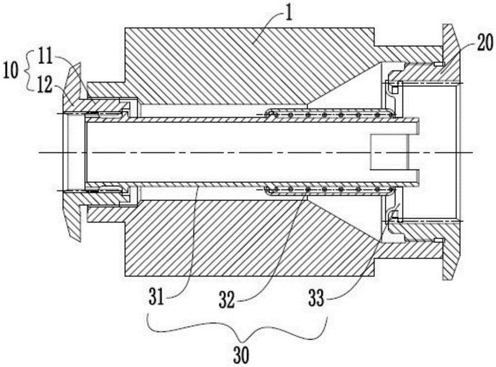
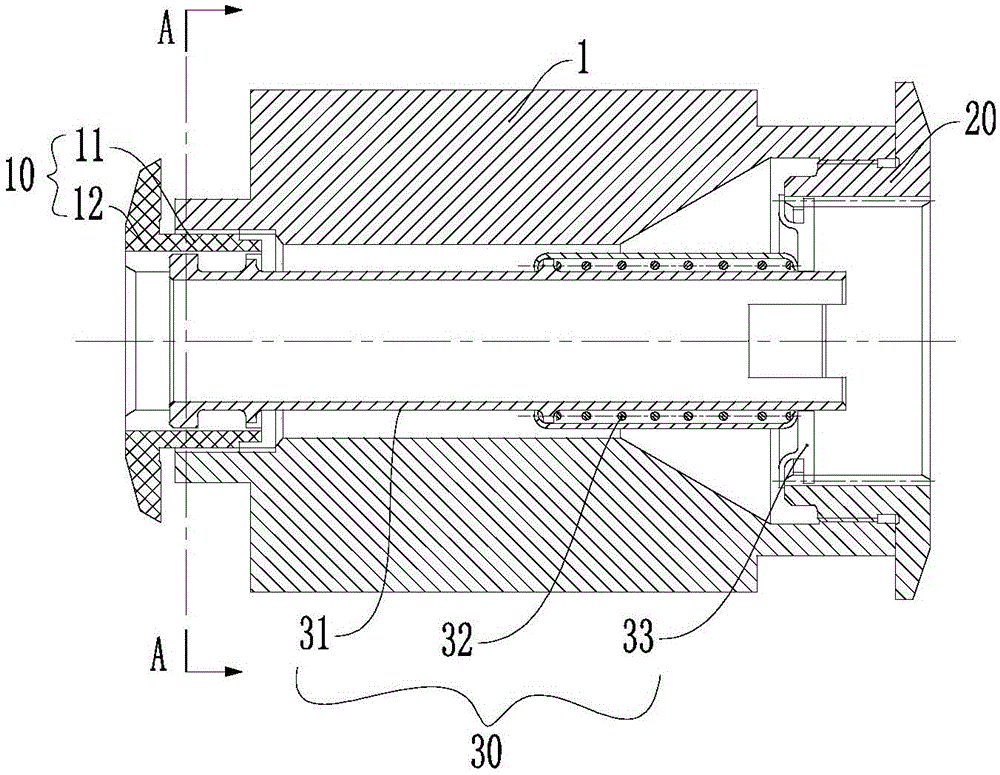
[0024] see figure 1 , the preferred embodiment of the present invention provides a locking device for locking the bearing installed on the rotor shaft 1; the locking device includes a lock nut 10, which is threadedly connected with the first end of the rotor shaft 1 for Lock the bearing installed between the lock nut 10 and the shoulder of the rotor shaft 1; the fixing part 20 is fixedly arranged on the second end of the rotor shaft 1; the self-locking assembly 30 is rigidly connected between the lock nut 10 and the fixing part 20 for fixing the lock nut 10 and the fixing piece 20 along the circumferential direction of the rotor shaft 1 . According to the locking device of the present invention, a lock nut 10 and a fixing member 20 are respectively...


PUM


Abstract

The invention provides a locking device which is used for locking a bearing arranged on a rotor shaft. The locking device comprises a locking nut, a fixed element and a self-lock assembly, wherein the locking nut is connected with the first end of the rotor shaft via a thread and is used for locking the bearing arranged between the locking nut and a shaft shoulder of the rotator shaft; the fixed element is fixed on the second end of the rotor shaft; the self-lock assembly is rigidly connected between the locking nut and the fixed element, and is used for fixing the locking nut and the fixed element along the circumferential direction of the rotor shaft. According to the locking device disclosed by the invention, the locking nut and the fixed element are respectively arranged at two ends of the rotor shaft, and the self-lock assembly is rigidly connected between the locking nut and the fixed element, so that the locking nut and the fixed element cannot rotate along the circumferential direction of the rotor shaft, so as to fix the locking nut and achieve the purpose of locking the bearing. A lock assembly is rigidly fixed through the self-lock assembly along the circumferential direction, so that the locking function of the locking device does not easily in failure. Therefore, the reliability of the locking device is improved.

Description

technical field [0001] The invention relates to the field of gas turbines, in particular to a locking device. Background technique [0002] The rotor shaft is the core component of the gas turbine. To ensure the normal operation of the rotor shaft, the rotor shaft of the gas turbine needs to be supported by bearings. Most of the bearings are fixed on the rotor shaft by corresponding compression nuts. In the actual working process, in order to prevent the compression nut from loosening, it is necessary to use anti-loosening measures. In the existing locking methods, the material deformation of parts such as lock pieces is mostly used to achieve the purpose of locking. However, the locking torque provided by the deformation of the material is not high. In the actual working process, the compression nut is subjected to a large loosening torque, and the lock plate and other parts will deform and fail due to excessive torque, thus losing the locking role, the reliability is not...

Claims


Application Information

Patent Timeline
Patent Type & Authority Applications(China)
IPC IPC(8): F16C35/08F16B39/10F02C7/06
Inventor 赵林黄谭喜谢卫红晏品义袁靖
Owner CHINA HANGFA SOUTH IND CO LTD
Why Eureka
Try Eureka