Measuring and calculating method for geometrical parameters of large-caliber off-axis aspheric optical element
An off-axis aspheric and optical element technology, applied in the field of optical detection, can solve the problem that the geometric parameters of large-diameter off-axis aspheric optical elements are difficult to accurately measure, and achieve the effect of improving the measurement accuracy
- Summary
- Abstract
- Description
- Claims
- Application Information
AI Technical Summary
Problems solved by technology
Method used
Image
Examples
specific Embodiment approach 1
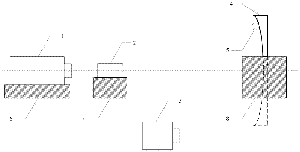
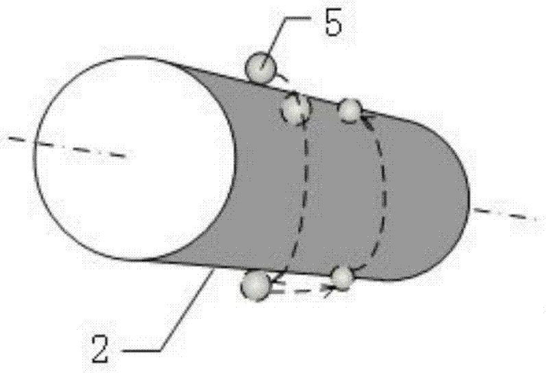
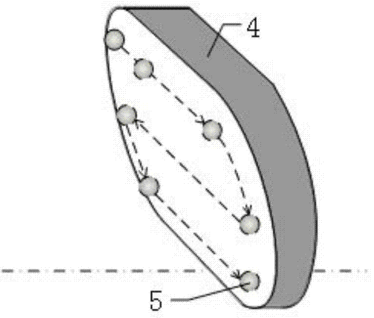
[0026] Specific implementation mode one, combination Figure 1 to Figure 6 In this implementation, the method for measuring and calculating the geometric parameters of the large-aperture off-axis aspheric optical element described in this implementation mode uses compensators, laser interferometers, laser trackers and regulators to measure and calculate the geometric parameters of the off-axis aspheric elements . The method flow is as follows:
[0027] Step 1. Adjust the relative positional relationship between the interferometer 1, the compensator 2 and the aspheric optical element 4 to be inspected through the interferometer position adjuster 6, the compensator position adjuster 7 and the aspheric optical element position adjuster 8 to be inspected. Observe and measure the output of the interferometer 1 to achieve zero fringes and the minimum surface error, so as to ensure that the three are coaxial.
[0028] Step 2: Fix the position of the adjuster corresponding to the interfer...
specific Embodiment approach 2
[0062] Specific implementation mode two, combination Figure 7 to Figure 10 To describe this embodiment, this embodiment is an example of using the method for measuring geometric parameters of a large-aperture off-axis aspheric optical element described in the first embodiment:
[0063] Step A: Adjust the relative positional relationship between the compensator, the interferometer and the aspheric element to be inspected, and observe and measure the output of the interferometer to achieve zero fringe and the minimum surface error to ensure that the three are coaxial.
[0064] Step B: Fix the relative positions of the interferometer, the compensator, and the aspheric elements to be inspected unchanged, and use the laser tracker to measure the coordinates of a group of compensator cylinders and the coordinates of a group of aspheric mirrors to be inspected.
[0065] Implement steps A and B, get [col_x 1 ,col_y 1 ,col_z 1 ;col_x 2 ,col_y 2 ,col_z 2 ;...Col_x m ,col_y m ,col_z m ] And [x...
PUM
 Abstract
Description
Claims
Application Information
 - R&D
- Intellectual Property
- Life Sciences
- Materials
- Tech Scout
- Unparalleled Data Quality
- Higher Quality Content
- 60% Fewer Hallucinations
Browse by: Latest US Patents, China's latest patents, Technical Efficacy Thesaurus, Application Domain, Technology Topic, Popular Technical Reports.
© 2025 PatSnap. All rights reserved.Legal|Privacy policy|Modern Slavery Act Transparency Statement|Sitemap|About US| Contact US: help@patsnap.com


