
Method for preventing machining deformation of thin-walled work-piece

A thin-walled part processing and to-be-processed technology, applied in the thin-walled part processing technology field, can solve problems such as processing deformation, and achieve the effect of preventing processing deformation and workpiece deformation

Active Publication Date: 2014-02-19
SHENYANG LIMING AERO-ENGINE GROUP CORPORATION
View PDF5 Cites 6 Cited by
  • Summary
  • Abstract
  • Description
  • Claims
  • Application Information

AI Technical Summary

Problems solved by technology

[0003] The purpose of this invention is to solve the problem of processing deformation of parts, correctly determine whether the dimensional accuracy and technical conditions of parts meet the requirements of the drawings, and provide a method for preventing processing deformation of thin-walled parts

Method used


Image

  • Method for preventing machining deformation of thin-walled work-piece
  • Method for preventing machining deformation of thin-walled work-piece
  • Method for preventing machining deformation of thin-walled work-piece

Examples


Embodiment 1

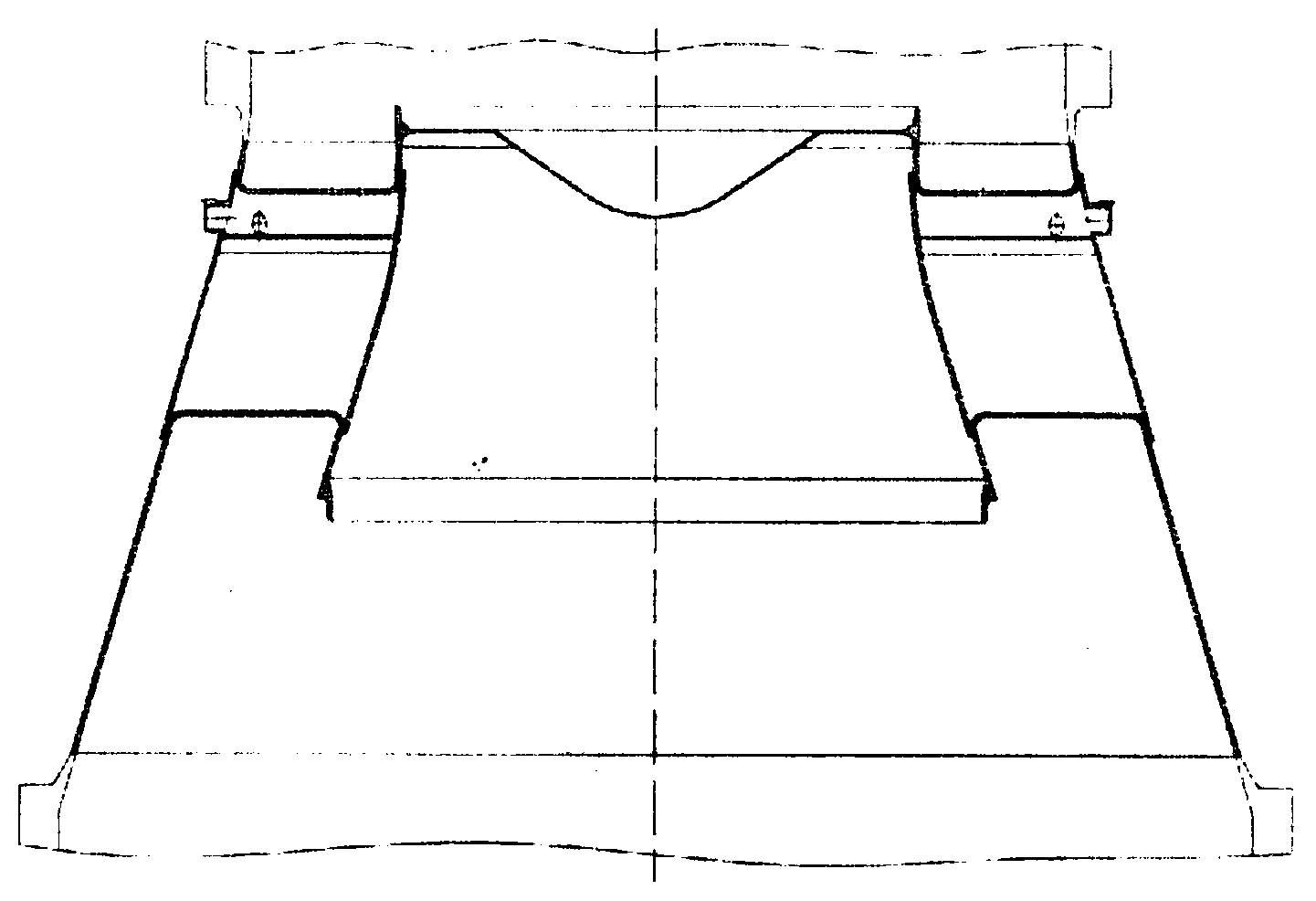
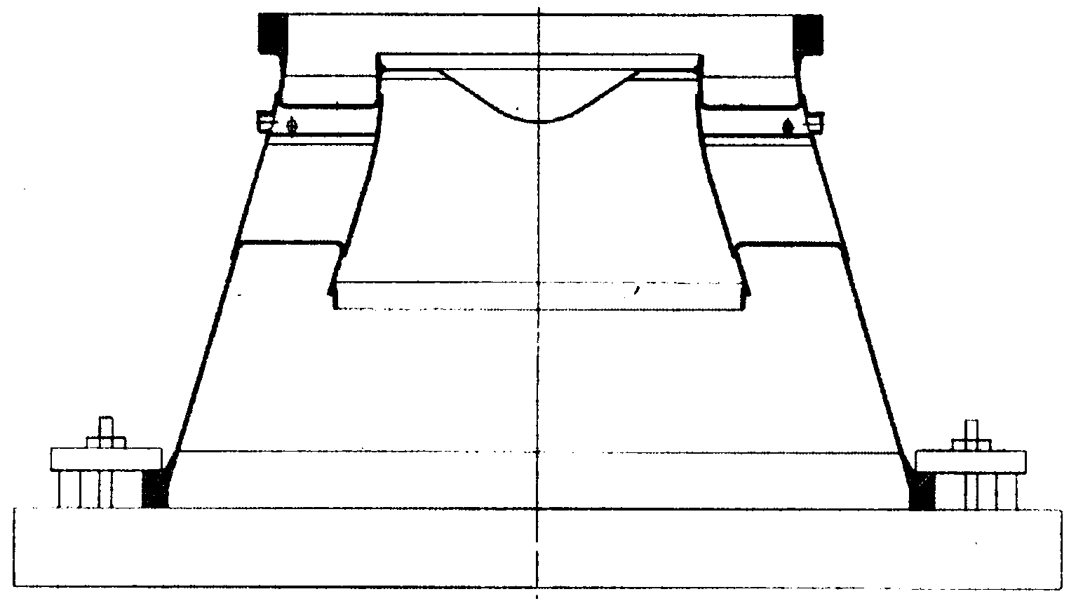
[0015] This embodiment provides a method for preventing processing deformation of thin-walled parts, which is characterized in that: the method for preventing processing deformation of thin-walled parts involves an outer circle with a size of 150-3000mm. For wall parts, it is required that the clamping method of the parts during processing is compression, and there are mounting edges at both ends of the processed parts. After processing to the required size, the process mounting edges are removed, and the parts are installed on the faceplate or chuck of the machine tool for compression. Align the point, rough machine the upper end surface and the outer circle or cone surface, turn around and align with the processed end surface and the outer circle of the installation edge, press the lower end surface, measure the deformation error of the processed end surface with a feeler gauge; then use the equal error After inserting the spacer or feeler gauge with the same value into the c...

Embodiment 2

[0019] This embodiment provides a method for preventing processing deformation of thin-walled parts, which is characterized in that: the method for preventing processing deformation of thin-walled parts involves an outer circle with a size of 150-3000mm. For wall parts, it is required that the clamping method of the parts during processing is compression, and there are mounting edges at both ends of the processed parts. After processing to the required size, the process mounting edges are removed, and the parts are installed on the faceplate or chuck of the machine tool for compression. Align the point, rough machine the upper end surface and the outer circle or cone surface, turn around and align with the processed end surface and the outer circle of the installation edge, press the lower end surface, measure the deformation error of the processed end surface with a feeler gauge; then use the equal error After inserting the spacer or feeler gauge with the same value into the c...

Embodiment 3

[0023] This embodiment provides a method for preventing processing deformation of thin-walled parts, which is characterized in that: the method for preventing processing deformation of thin-walled parts involves an outer circle with a size of 150-3000mm. For wall parts, it is required that the clamping method of the parts during processing is compression, and there are mounting edges at both ends of the processed parts. After processing to the required size, the process mounting edges are removed, and the parts are installed on the faceplate or chuck of the machine tool for compression. Align the point, rough machine the upper end surface and the outer circle or cone surface, turn around and align with the processed end surface and the outer circle of the installation edge, press the lower end surface, measure the deformation error of the processed end surface with a feeler gauge; then use the equal error After inserting the spacer or feeler gauge with the same value into the c...


PUM


Abstract

Disclosed is a method for preventing machining deformation of a thin-walled work-piece. The two ends of the machined work-piece are respectively provided with an installation edge, the installation edges are removed after the work-piece is machined to be of the required size, the work-piece is installed on a disc chuck or a chuck of a machine tool to be pressed tightly, point countering and alignment are carried out, the upper end face and outer circles or cone faces are machined in a rough mode, the work-piece turns around and aligns using the machined end face and the machined outer circles of the installation edges, the lower end face is pressed tightly, and deformation errors of the machined end faces are measured through a filler gauge; after a gasket or filler gauge of the equal error value is used for being plugged to the corresponding position of an error protrusion at the bottom face, the work-piece is pressed tightly by a handle board, then the other face is machined in a rough mode, the work-piece turns around, and semi-fine turning is carried out on the upper end and the outer circles or the cone faces; the semi-fine turning is carried out step by step, when the allowance for machining is 0.5-1mm, the work-piece is released and placed in a free mode, alignment is carried out again, point countering and alignment are carried out on the outer circles of the installation edges, and fine machining and semi-fine machining are the same in method. The method for preventing machining deformation of the thin-walled work-piece has the advantages that deformation of the workpiece in the machining process is avoided, and whether the dimensional accuracy, technical conditions and the like meet the requirements can still be measured accurately when the work-piece is located at the free state.

Description

technical field [0001] The invention relates to the field of processing technology of thin-walled parts, in particular to a method for preventing deformation of thin-walled parts during processing. Background technique [0002] Thin-walled parts such as sleeves and cones have large deformation during processing, which brings great difficulties to the alignment and measurement of parts during finishing, and the size and technical conditions of most parts can only be limited by the machine tool. Under the measurement, the part cannot be measured due to the deformation caused by the processing stress in the free state, resulting in the inability to correctly judge whether the dimensional accuracy and technical conditions of the part meet the requirements of the drawing. Contents of the invention [0003] The purpose of the present invention is to solve the problem of processing deformation of parts, correctly determine whether the dimensional accuracy and technical conditions...

Claims


Application Information

Patent Timeline
IPC IPC(8): B23B1/00
CPCB23B1/00
Inventor 王洪斌王云利张宝成
Owner SHENYANG LIMING AERO-ENGINE GROUP CORPORATION
Learn More