Closed riser indirect evaporative cooling high temperature chiller

An evaporative cooling and chiller technology, which is used in evaporators/condensers, refrigerators, refrigeration components, etc., can solve problems such as difficulty in meeting water quality control requirements, high water quality requirements, and limited applicability, and achieve reduced size. , The effect of reducing water temperature and improving heat exchange efficiency

Active Publication Date: 2015-11-18
新疆华奕新能源科技有限公司
View PDF6 Cites 0 Cited by
  • Summary
  • Abstract
  • Description
  • Claims
  • Application Information

AI Technical Summary

Problems solved by technology

In Northwest China, open evaporative cooling high-temperature chillers have been put into use due to the large windy and sandy atmospheric environment in Northwest my country. The blockage and water quality changes caused by windy sand have caused great limitations to the popularization and use of evaporative cooling chillers.
At the same time, in terms of unit size, the commonly used tubular indirect evaporative cooler, due to the limitation of its structure, leads to a large size of evaporative cooling high-temperature chiller, and its applicability is limited in some places.
[0003] In some special places of use, such as in the air-cooling system of power plants, the circulating water used is demineralized water, which has high requirements on water quality. It is difficult for ordinary open-type evaporative cooling high-temperature chillers to meet their water quality control requirements. Areas where air-cooling systems are widely used are often areas where evaporative cooling technology is more suitable

Method used


Image

  • Closed riser indirect evaporative cooling high temperature chiller
  • Closed riser indirect evaporative cooling high temperature chiller
  • Closed riser indirect evaporative cooling high temperature chiller

Examples


Embodiment Construction

[0022] The present invention will be described in detail below in conjunction with the accompanying drawings and specific embodiments.

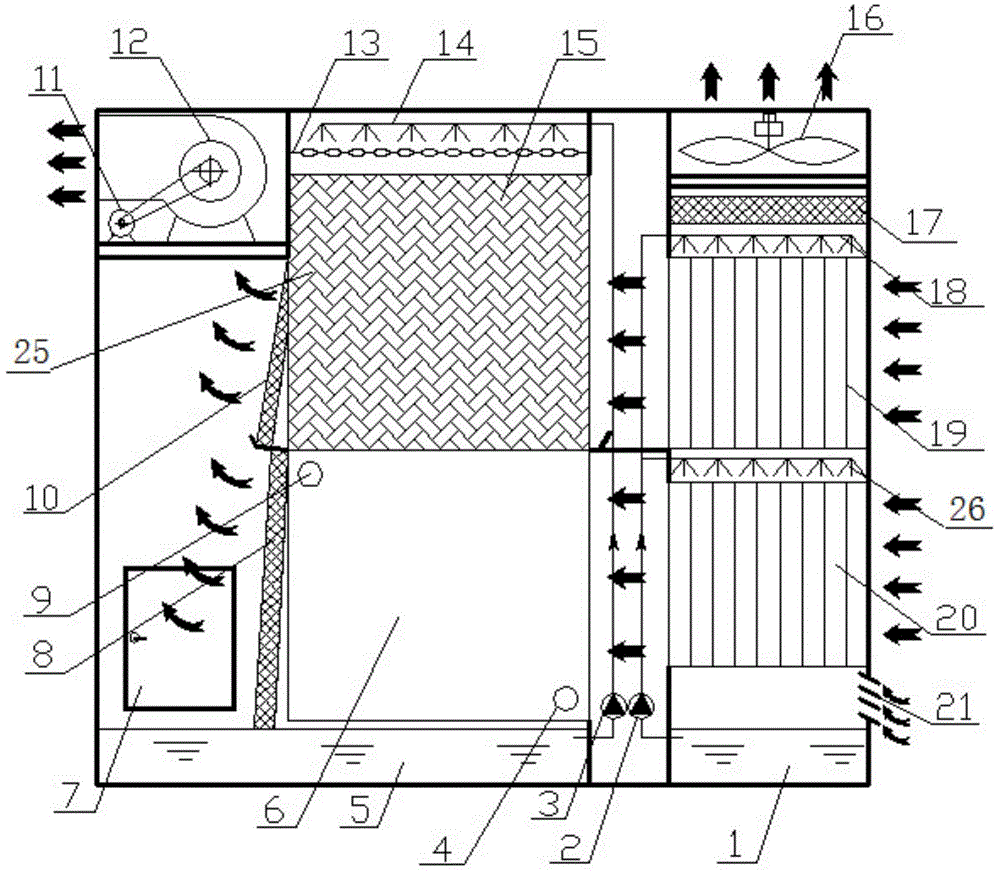
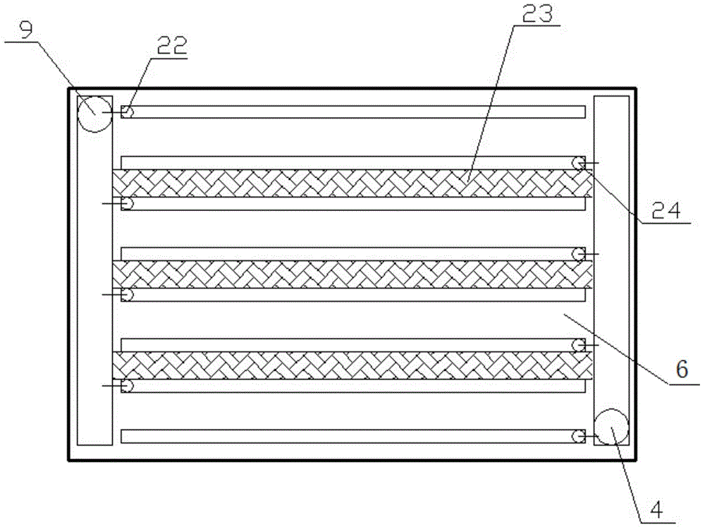
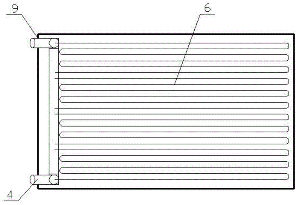
[0023] The structure of the high-temperature water chiller with closed standpipe indirect evaporative cooling of the present invention is as follows: figure 1 As shown, it includes vertical pipe indirect evaporative cooler a19 and vertical pipe indirect evaporative cooler b20 arranged up and down at the air inlet in the unit shell, and the lower part of vertical pipe indirect evaporative cooler b20 is the secondary air inlet 21 , according to the air inlet direction, a direct evaporative cooler 25, a water baffle b10 and a centrifugal fan 12 are arranged in turn behind the standpipe indirect evaporative cooler a19, and a closed cooling fan 12 is arranged in turn behind the standpipe indirect evaporative cooler b20. The heater 6, the water baffle a8, and the upper part of the vertical tube indirect evaporative cooler a19 are provided with a wa...


PUM


Abstract

The closed standpipe indirect evaporative cooling high-temperature water chiller disclosed by the present invention includes a standpipe indirect evaporative cooler a and a standpipe indirect evaporative cooler b arranged up and down at the air inlet in the casing of the unit, and the standpipe indirect evaporative cooler b. The lower part of the cooler b is the secondary air inlet. According to the air inlet direction, a direct evaporative cooler, a water baffle b and a centrifugal fan are arranged in sequence behind the vertical pipe indirect evaporative cooler a. The vertical pipe indirect evaporative cooler a A closed heat exchanger and a water baffle a are arranged in sequence behind b, and a water baffle c and an axial flow fan are arranged in sequence on the upper part of the standpipe type indirect evaporative cooler a from bottom to top. The present invention adopts vertical pipe-type indirect evaporative coolers arranged up and down, direct evaporative coolers and closed heat exchangers arranged up and down, respectively controls the primary air and secondary air through the centrifugal fan and the axial flow fan, and jointly forms a chiller unit to ensure that the cold water The water quality and outlet temperature of the unit have improved the heat exchange efficiency of the unit to a certain extent.

Description

technical field [0001] The invention belongs to the technical field of air conditioning equipment, and in particular relates to a closed vertical pipe indirect evaporative cooling high-temperature water chiller combined with a closed heat exchanger, a vertical pipe indirect evaporative cooler and a direct evaporative cooler. Background technique [0002] As an efficient cooling technology, evaporative cooling technology is not only widely used in the production of cold air, but also in the production of cold water based on its principle, and it is also becoming mature step by step. In Northwest China, open evaporative cooling high-temperature chillers have been put into use due to the large windy and sandy atmospheric environment in Northwest my country. The blockage and water quality changes caused by windy sand have caused great limitations to the promotion and use of evaporative cooling chillers. At the same time, in terms of unit size, the tube-type indirect evaporative ...

Claims


Application Information

Patent Timeline
Patent Type & Authority Patents(China)
IPC IPC(8): F25B41/00F25B39/00F25B41/40
Inventor 黄翔邱佳宋祥龙王俊董晓杰
Owner 新疆华奕新能源科技有限公司
Why Eureka
Try Eureka