Test method for urea crystallization in scr exhaust gas treatment system of engine

A tail gas treatment and engine technology, applied in the electronic control of exhaust treatment devices, diagnostic devices of exhaust treatment devices, exhaust treatment, etc., can solve problems such as excessive emissions, failure to meet emission requirements, blockages, etc.

Active Publication Date: 2015-11-18
BEIQI FOTON MOTOR CO LTD
View PDF8 Cites 3 Cited by
  • Summary
  • Abstract
  • Description
  • Claims
  • Application Information

AI Technical Summary

Problems solved by technology

[0003] However, due to the unique chemical properties of the urea solution itself, different products are produced at different operating temperatures, resulting in different products on the front pipe section of the exhaust treatment device 5 due to the different operating conditions of the vehicle engine. Fluid or crystals are formed, and the crystals are usually blocked on the mesh of the atomizer 7 under the blowing of the exhaust gas, thereby affecting the passage of the atomized urea solution, exhaust gas and its mixed gas
Generally speaking, if the ratio of the clogged area to the cross-section of the atomizer 7 exceeds a certain value (for example, 40%), the function of the SCR system will be greatly affected
If there is a large amount of such fluid or crystals, it will affect the atomization of urea solution and the passage of exhaust gas, which will cause the back pressure of the SCR exhaust gas treatment system to increase, increase the engine power loss, and to a large extent Affect the atomization quality of urea solution, directly lead to incomplete tail gas reaction, resulting in excessive emission, thus failing to meet emission requirements
In the prior art, there is no perfect method for checking whether the urea crystallization is qualified in the process of system development. Therefore, it is impossible to verify in advance whether the engine SCR system matched with the vehicle meets the requirements during the development process, thereby increasing the market. Risk of crystallization problems leading to problems with aftertreatment systems not working properly

Method used


Image

  • Test method for urea crystallization in scr exhaust gas treatment system of engine
  • Test method for urea crystallization in scr exhaust gas treatment system of engine
  • Test method for urea crystallization in scr exhaust gas treatment system of engine

Examples


Embodiment Construction

[0025] Specific embodiments of the present invention will be described in detail below in conjunction with the accompanying drawings. It should be understood that the specific embodiments described here are only used to illustrate and explain the present invention, and are not intended to limit the present invention.

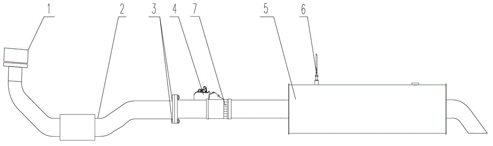
[0026] In the present invention, unless stated otherwise, the orientation words used such as "left, right, front, rear" are usually directed to the direction shown in the drawings, especially to the SCR exhaust gas treatment system of the engine In terms of the flow direction of the exhaust gas inside, that is, the exhaust gas flows from "front" to "rear", and from "left" to "right".

[0027] combine figure 1 , the present invention provides a urea crystallization test method for the SCR exhaust gas treatment system of the engine, the test method includes: a first step: within a test cycle, the engine is sequentially and continuously tested under a variety of p...


PUM


Abstract

The invention discloses a urea crystallization detecting and testing method of an SCR tail gas treatment system of an engine, The method includes the steps of firstly, in a testing cycle, allowing the engine to sequentially and continuously work under various preset testing work conditions; secondly, after the testing cycle, calculating the ratio of the area of urea crystal substances accumulated on the cross section of the atomizer (7) of the SCR tail gas treatment system to the area of the cross section of the atomizer (7) to obtain the blocking area ratio. The method can further include a third step: repeating the first step and the second step to obtain each blocking area ratio of the atomizer (7) in multiple testing cycles. If the blocking area ratio in an optional testing cycle is larger than the preset blocking area ratio standard E, the SCR tail gas treatment system does not meet the requirements, and the mounting structure of the SCR tail gas treatment system needs to be optimized and adjusted.

Description

technical field [0001] The invention relates to an SCR exhaust gas treatment system of an engine, in particular to a urea crystallization testing method of the SCR exhaust gas treatment system of an engine. Background technique [0002] like figure 1 As shown, when the SCR exhaust gas treatment system of the engine (especially the diesel engine) is applied to the whole vehicle, the exhaust gas of the engine passes through the engine exhaust port 1 and the exhaust pipe 2 and passes through the urea nozzle 4 and the atomizer 7. The front pipe section of the exhaust treatment device is discharged into the exhaust treatment device 5 for catalytic reduction reaction. Wherein, on the front pipe section of the exhaust gas treatment device 5, the urea solution nozzle 4 sprays out the urea solution injection amount according to the engine electronic control unit, and the sprayed urea solution sprays to the grid-shaped space provided in front of the urea solution nozzle 4. Atomizer ...

Claims


Application Information

Patent Timeline
Patent Type & Authority Patents(China)
IPC IPC(8): F01N11/00
CPCY02T10/40
Inventor 李坤何翠莲宋晶晶李国红张文明
Owner BEIQI FOTON MOTOR CO LTD
Why Eureka
Try Eureka