
Device for turning over cop and cop bobbin

A bobbin and bobbin technology, applied in transportation and packaging, textile and papermaking, thin material processing, etc., can solve problems such as elastic liner wear and tear

Active Publication Date: 2014-02-12
SAURER SPINNING SOLUTIONS GMBH & CO KG
View PDF11 Cites 11 Cited by
  • Summary
  • Abstract
  • Description
  • Claims
  • Application Information

AI Technical Summary

Problems solved by technology

[0011] The device of EP0475485A1 can only be operated with limited productivity, because the disc has to clamp the cop foot and cannot be rotated arbitrarily fast
The disc clamps the cop foot and wears out the elastic pad

Method used


Image

  • Device for turning over cop and cop bobbin
  • Device for turning over cop and cop bobbin
  • Device for turning over cop and cop bobbin

Examples


Embodiment Construction

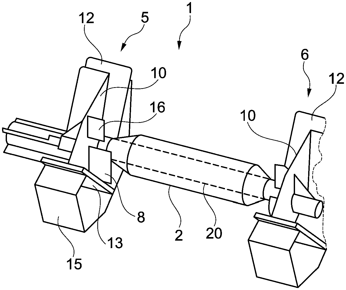
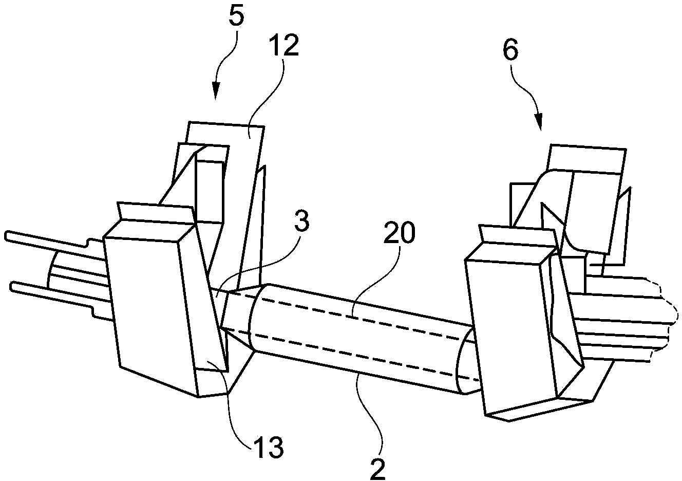
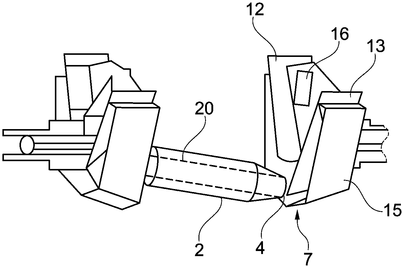
[0041] figure 1 The device 1 according to the invention for inverting bobbins 2 and bobbins 20 is shown. The function of the device 1 will be described below with respect to the bobbin 2 . However, this function also applies to the cop bobbin 20 as well. The cop bobbins 20 , which are largely covered by the winding of the cop 2 , are indicated by dashed lines. The device 1 has two opposite holders 5 and 6 for bobbin ends, wherein the holders 5 , 6 are arranged and formed symmetrically with respect to a horizontal plane lying between the two holders 5 , 6 . Each bracket 5 , 6 is configured as a funnel-shaped profile 11 formed by two funnel plates 12 , 13 . The funnel plates 12 and 13 are mounted on a profile 15 .

[0042] Figure 10 Only the profiled part 15 is shown. The profiled part 15 has two inserts 18 for the funnel plates 12 , 13 . Figure 11 The profile with the funnel plates 12 and 13 installed is shown in side view. The funnel plate 13 now extends as far as th...


PUM


Abstract

The invention relates to a device for turning over a cop and a cop bobbin. The device is configured to enable the cop or the cop bobbin with a cop foot ahead to drop downwards. The device comprises brackets used for two cop ends and having a gap which is such configured that a cop head passes through the gap while the cop foot does not; amd holding mechanisms, each of which is arranged under the brackets to be such configured that the holding mechanisms support the cop head. According to the device for turning over the cop and the cop bobbin, the holding mechanisms are such configured that the cop supported by virtue of the cop head or the cop bobbin supported by virtue of the cop head can move along a horizontal direction; and control mechanisms are arranged, which are attached to the brackets respectively and are such configured that the cop head supported by the holding mechanisms is not grasped by the control mechanisms when the control mechanisms are controlled, and the cop foot located in the brackets is grasped by the control mechanisms and moves along the horizontal direction when the control mechanisms are controlled.

Description

technical field [0001] The invention relates to a device for turning (wenden) bobbins and bobbin bobbins which are delivered horizontally in any orientation, each having a bobbin end formed with a larger diameter as the bobbin foot and the cop end formed as the cop end with a smaller diameter, so that the cop or cop bobbin falls downwards with the cop foot first. The device comprises a socket respectively for one of the bobbin ends with a gap, wherein the two sockets are opposite each other and arranged and formed symmetrically with respect to a vertical plane, the gaps being respectively formed such that the bobbin end passes through the gap without the cop foot passing through the gap. In addition, the device comprises holding means which are arranged under each bracket and are configured such that the holding means supports the bobbins of the bobbins or the bobbin bobbins and thereby prevents said bobbins from Dropped, the bobbin foot of the bobbin or the bobbin foot of t...

Claims


Application Information

Patent Timeline
IPC IPC(8): D01H9/02
CPCB65G47/256B65H67/061B65H2701/31D01H9/18
Inventor S·本特尔诺伯特·科雷斯J·佩尔塞克
Owner SAURER SPINNING SOLUTIONS GMBH & CO KG
Learn More