
Tool holder and tool holder attachment structure

一种工具保持、安装结构的技术,应用在制造工具、金属加工机械零件、定位装置等方向,能够解决无法主轴安装工具保持件等问题

Active Publication Date: 2014-02-12
NIKKEN KOSAKUSHO WORKS LTD
View PDF7 Cites 0 Cited by
  • Summary
  • Abstract
  • Description
  • Claims
  • Application Information

AI Technical Summary

Problems solved by technology

However, due to the allowable production error Δi, for example, the amount of the spindle end protruding forward, the end surface of the spindle will abut the flange end surface of the tool holder before the tapered hole 2 and the tapered shank 4 are in close contact, so the tapered hole There will be a gap between the tapered shank and the tool holder cannot be securely installed on the spindle

Method used


Image

  • Tool holder and tool holder attachment structure
  • Tool holder and tool holder attachment structure
  • Tool holder and tool holder attachment structure

Examples


Embodiment Construction

[0034] The invention is particularly applicable to tool holder mounting structures of the BT type in which the tapered shank of the tool holder is positioned within the tapered bore of the spindle.

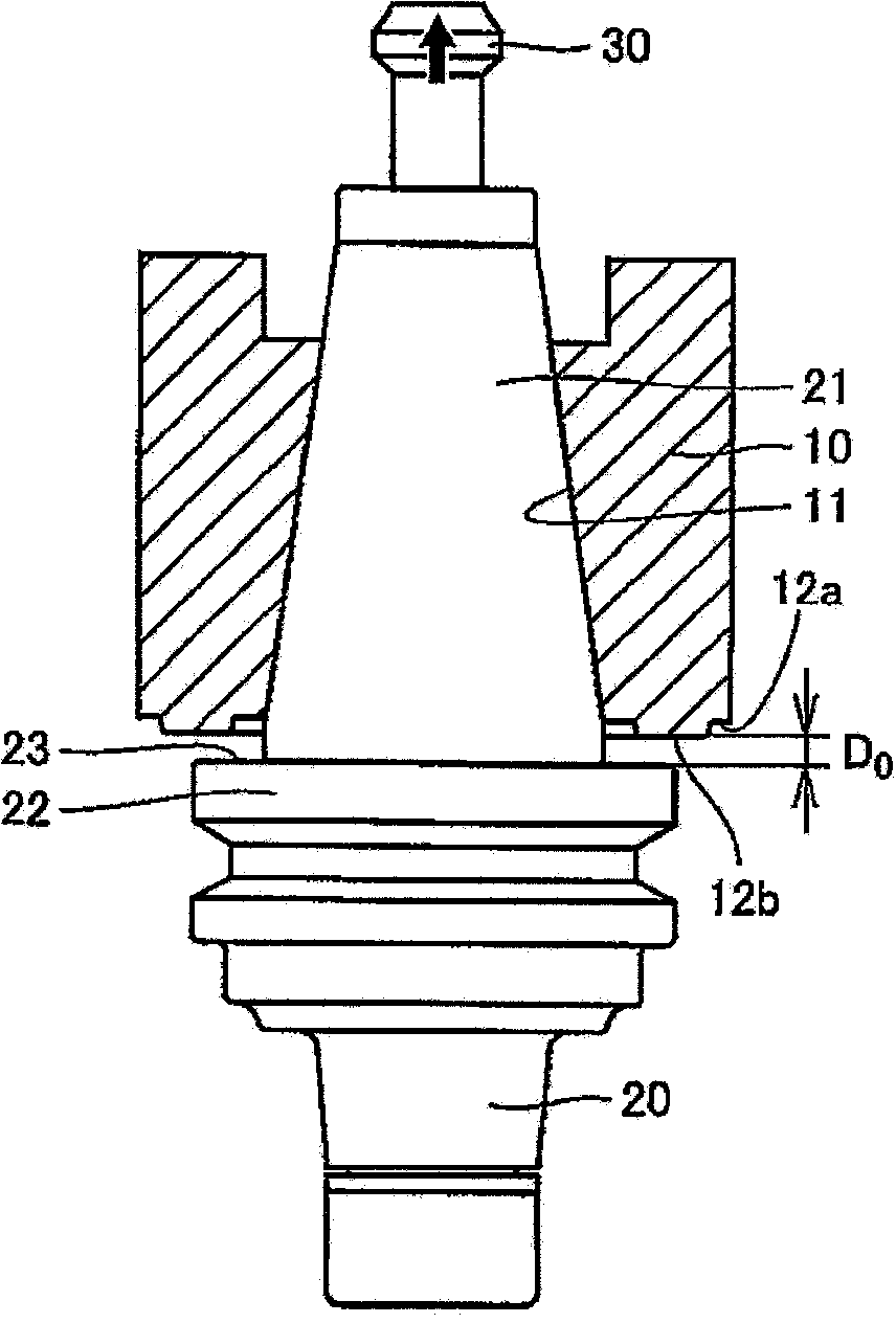
[0035] figure 1 It is a cross-sectional view showing a state where the tool holder is attached to the tapered hole of the main shaft of the machine tool. The main shaft 10 has a tip surface 12 a serving as a reference end surface and a tapered hole 11 extending axially inward from the tip surface 12 a.

[0036] The tool holder 20 includes a tapered shank portion 21 and a collar portion 22 , wherein the tapered shank portion 21 fits into the tapered hole 11 of the spindle 10 , and the collar portion 22 is held by a manipulator during automatic tool exchange. The flange portion 22 has a flange portion end surface 23 facing the distal end surface 12 a of the main shaft 10 .

[0037] figure 1 It shows a state where the tapered shank portion 21 of the mounting tool holder 20 is in...


PUM


Abstract

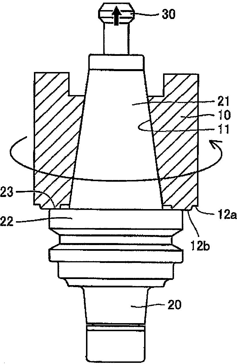
A tool holder attachment structure includes a spindle (10) and a tool holder (20). The spindle has a tip end face (12b) and a tapered hole (11). The tool holder has a tapered shank portion (21) and a flange end face (23). In a clamped state, there is a clearance (D1) of a predetermined size between the flange end face of the tool holder and the tip end face of the spindle. As the spindle is rotated, the tapered hole of the spindle is slightly expanded by a centrifugal force caused by rotation of the spindle, and the presence of this clearance allows the tapered shank portion to be further drawn into the tapered hole so that the flange end face of the tool holder closely contacts the tip end face of the spindle, and the tapered shank portion is closely fitted in the tapered hole, whereby two-face restraint is implemented.

Description

technical field [0001] The present invention relates to a tool holder installation structure for installing a tool holder provided with a cutting tool to a machining center with an automatic tool exchange device, etc., and a tool holder installed on a rotating spindle. Mechanical rotating spindle. Background technique [0002] For example, Japanese Patent No. 2571325 (Patent Document 1) discloses such a tool holder mounting structure. Figure 4 It is a drawing corresponding to FIG. 5 of the above publication, and shows a structure in which the tool holder is attached to the main shaft of the machine tool. [0003] A tool holder 3 for a machining center with an automatic tool changer comprises a tapered shank 4 and a Manipulator grip collar 5 adjoining said tapered shank 4 for automatic tool exchange, and It is integrally formed with the taper shank 4 . The tool holder 3 is drawn and clamped into the tapered hole 2 of the main shaft 1 of the working machine by the drawing b...

Claims


Application Information

Patent Timeline
Patent Type & Authority Applications(China)
IPC IPC(8): B23Q3/12
CPCB23B31/268B23B2231/0204B23B31/006B23B31/261Y10T409/30952Y10T409/309408B23C5/26B23Q3/12B23B2231/0292
Inventor 三角进
Owner NIKKEN KOSAKUSHO WORKS LTD
Learn More