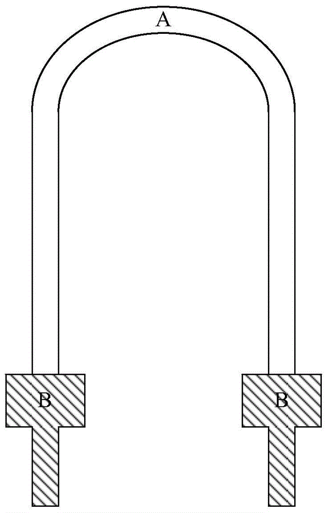
Shunting element for printed circuit board
A technology for printed circuit boards and shunt components, which is applied to printed circuit components, resistive elements adjusted by short-circuiting different numbers of resistive elements, and contact parts. Advanced problems, to achieve the effect of increasing average output, simple structure and cost saving
- Summary
- Abstract
- Description
- Claims
- Application Information
AI Technical Summary
Problems solved by technology
Method used
Image
Examples
specific Embodiment approach
[0021] In order to make the object, technical solution and advantages of the present invention clearer, the present invention will be further described in detail below in conjunction with the accompanying drawings and embodiments. It should be understood that the specific embodiments described here are only used to explain the present invention, not to limit the present invention.
[0022] Aiming at the problems existing in the prior art, the present invention proposes a shunt element for a printed circuit board. The shunt element is formed by bending a strip-shaped metal sheet, and at least one notch is formed on the opposite first end and second end of the strip-shaped metal sheet, so that the first end is divided into at least one first-type pin and at least one A pin of the second type, the second end is divided into at least one pin of the third type and at least one pin of the fourth type, and the width of the pin of the first type is greater than that of the pin of the ...
Embodiment 1
[0024] Embodiment 1 of the present invention proposes a shunt element of a printed circuit board, the shunt element adopts a center sampling structure, such as figure 2 It is an extended schematic diagram of the shunt element of the printed circuit board provided by Embodiment 1 of the present invention, image 3 It is a three-dimensional structure schematic diagram of the shunt element of the printed circuit board provided by Embodiment 1 of the present invention. The three-dimensional structure schematic diagram is an example of bending a strip metal sheet into an m shape. Of course, it can also be bent into an n shape according to the actual situation of the printed circuit board. shape or any other shape. For illustrative purposes, figure 2 and image 3 Only the parts related to Embodiment 1 of the present invention are shown.
[0025] In detail, combine figure 2 and image 3 As shown, the shunt element of the printed circuit board provided by Embodiment 1 of the p...
Embodiment 2
[0034] Embodiment 2 of the present invention proposes a shunt element of a printed circuit board, the shunt element adopts a cross-average sampling structure, such as Image 6 It is an extended schematic diagram of the shunt element of the printed circuit board provided by the second embodiment of the present invention, Figure 7 It is a three-dimensional structure schematic diagram of the shunt element of the printed circuit board provided by the second embodiment of the present invention. The three-dimensional structure schematic diagram is an example of bending a strip metal sheet into an m shape. Of course, it can also be bent into an n shape according to the actual situation of the printed circuit board. shape or any other shape. For illustrative purposes, Image 6 and Figure 7 Only the parts related to Embodiment 2 of the present invention are shown.
[0035] In detail, combine Image 6 and Figure 7 As shown, the shunt element of the printed circuit board provided...
PUM
 Abstract
Description
Claims
Application Information
 - R&D
- Intellectual Property
- Life Sciences
- Materials
- Tech Scout
- Unparalleled Data Quality
- Higher Quality Content
- 60% Fewer Hallucinations
Browse by: Latest US Patents, China's latest patents, Technical Efficacy Thesaurus, Application Domain, Technology Topic, Popular Technical Reports.
© 2025 PatSnap. All rights reserved.Legal|Privacy policy|Modern Slavery Act Transparency Statement|Sitemap|About US| Contact US: help@patsnap.com


