
A low-pressure condensate flash steam condenser and system for an mtp device

A technology of steam condenser and condensate, which is applied in the field of low-pressure condensate flash steam condenser and system of the improved MTP device, which can solve the problems of large pressure drop of the condenser, large heat exchange area, and pressure rise of the flash tank, etc. , to achieve the effect of increasing the heat transfer temperature difference, reducing the heat transfer area, and reducing the overpressure

Active Publication Date: 2016-11-30
BC P INC CHINA NAT PETROLEUM CORP +1
View PDF5 Cites 0 Cited by
  • Summary
  • Abstract
  • Description
  • Claims
  • Application Information

AI Technical Summary

Problems solved by technology

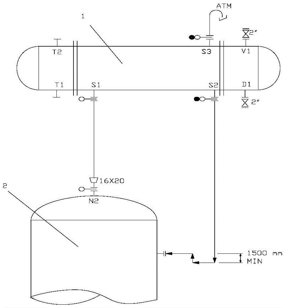
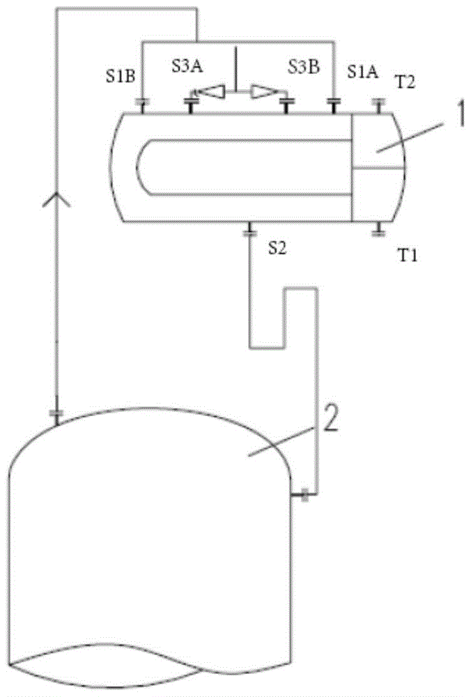
[0003] The existing condenser type and low-pressure condensate flash system are unreasonable, which makes the flash steam system unable to form a stable flow due to the low flow rate of the cold medium and the large flash volume of the flash tank when the device is started. The condensate flows into the flash tank from the steam inlet S1, and the condensate is also discharged from the vent port S3 from time to time. The pressure of the flash tank keeps rising, and the operation is extremely unstable. In addition, the pressure drop of the existing condenser is large, and the dew point drops significantly. The logarithmic average temperature difference between the hot and cold sides of the condenser is small, the required heat exchange area is large, and the equipment investment cost is high
[0004] Therefore, there is an urgent need to improve the existing low-pressure condensate flash steam condenser and low-pressure condensate flash system to solve the problem of backflow of condensate in the low-pressure condensate flash steam condenser and water discharge from the vent port in the prior art. , unstable operation, etc.

Method used


Image

  • A low-pressure condensate flash steam condenser and system for an mtp device
  • A low-pressure condensate flash steam condenser and system for an mtp device
  • A low-pressure condensate flash steam condenser and system for an mtp device

Examples


Embodiment 1

[0028] In the MTP plant with a scale of 500,000 tons / year of propylene, the low and low pressure condensate flash steam condenser in the atmospheric pressure condensate flash system, the steam volume from the flash tank is 46.8t / h, and the inlet temperature is 102℃ , the pressure is 99KPa, the required outlet temperature is 98°C, and the allowable pressure drop is 5KPa; the inlet and outlet temperatures of the cold medium desalinated water are 49°C and 87°C, respectively.

[0029] Using the existing steam condenser structure for design, the calculated pressure drop is 14KPa, the logarithmic average temperature difference is 23.5℃, and the required heat exchange area is 1190m 2 ;

[0030] The low-pressure condensate flash vapor condenser of the MTP device of the invention is used for design, the calculated pressure drop is 2KPa, the logarithmic average temperature difference is 26.2°C, and the required heat exchange area is 950m 2 ;

[0031] Therefore, under the industrial op...

Embodiment 2

[0033] In the 800,000 tons / year ethylene plant, the low and low pressure condensate flash steam condenser in the atmospheric condensate flash system, the steam volume from the flash tank is 21.43t / h, the inlet temperature is 105°C, and the pressure is 120KPa, the outlet temperature is required to be 100°C, and the allowable pressure drop is 20KPa; the inlet and outlet temperatures of the cold medium desalinated water are 54°C and 92°C, respectively.

[0034] Using the existing steam condenser structure to design, the calculated pressure drop is 13KPa, the logarithmic average temperature difference is 25.1℃, and the required heat exchange area is 791m 2 ;

[0035] The steam condenser proposed by the present invention is used for design, the calculated pressure drop is 2KPa, the logarithmic average temperature difference is 26.9°C, and the required heat exchange area is 712m 2 ;

[0036] Therefore, under the industrial operating conditions described in this example, the low-pr...


PUM


Abstract

The present invention relates to a low-pressure condensate flashing steam condenser and system of MTP device, and its purpose is to provide a low-pressure condensate flashing system of MTP device with low investment and stable operation. There is a steam inlet and a vent, a condensate outlet at the bottom, and a heat exchange line in the middle. One end of the heat exchange line is a refrigerant inlet, and the other end is a refrigerant outlet. The steam outlet of the condensate flash tank is connected to the steam. The steam inlet of the condenser, and the condensate outlet of the steam condenser is connected to the condensate inlet of the condensate flash tank.

Description

technical field [0001] The invention relates to an improved low-pressure condensate flashing steam condenser and a system of an MTP device, so as to solve the problems of condensate backflow, vent outlet water, unstable operation and the like in the low-pressure condensate flashing steam condenser in the prior art . Background technique [0002] At present, the low and low pressure condensate flash steam condensers in the existing MTP devices are all of fixed tube sheet type, such as figure 1 As shown in the figure, the cooling medium is desalinated water, and it goes through the pipe. In the existing design scheme, in order to simplify the piping, the steam flashed from the condensate flash tank enters the condenser from the bottom through the steam inlet S1, and is cooled and condensed by the desalination. , and then return to the condensate flash tank from the condensate outlet S2. In order to prevent the flash steam from entering the condenser from the condensate outle...

Claims


Application Information

Patent Timeline
Patent Type & Authority Patents(China)
IPC IPC(8): F28B1/02
Inventor 杨桂春李玉鑫朱为明王勇曹新波路聿轩苏燕兵孙文强
Owner BC P INC CHINA NAT PETROLEUM CORP
Learn More