Slide block control system of hydraulic machine

A hydraulic control system and control system technology, applied in the field of hydraulic presses, can solve problems such as inaccurate calculation and large errors, and achieve the effects of accurate calculation of return speed, low noise and high energy consumption

Active Publication Date: 2014-02-05
江苏扬力液压装备有限公司
View PDF6 Cites 14 Cited by
  • Summary
  • Abstract
  • Description
  • Claims
  • Application Information

AI Technical Summary

Problems solved by technology

When the slider moves down quickly, the oil in the lower chamber of the master cylinder returns to the oil tank through the cartridge valve. The speed of the slider is determined by various factors such as the weight of the moving parts, the resist

Method used


Image

  • Slide block control system of hydraulic machine
  • Slide block control system of hydraulic machine

Examples


Embodiment Construction

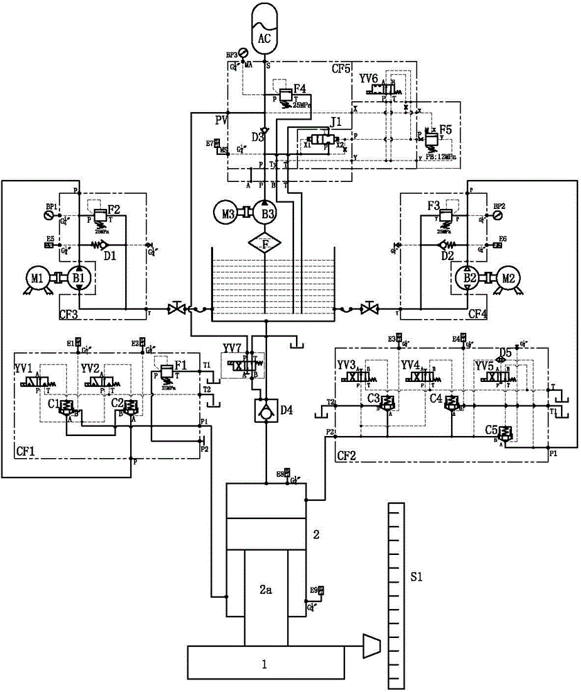
[0038] like figure 1 As shown, the slider control system of the hydraulic press of the present invention includes a slider 1, a column, a master cylinder 2, a hydraulic control system and an electrical control system. The lower end of the piston rod 2a of the master cylinder 2 is connected to the upper end of the slider 1, and the slider 1 Driven by the piston rod of the master cylinder, it can move up and down along the column guide rail. A displacement sensor S1 is installed on one side of the slider 1 to detect the moving position of the slider. The hydraulic chamber of the master cylinder is divided into an upper chamber and a lower chamber by the piston rod. An eighth pressure sensor E8 for detecting the pressure in the upper chamber is installed, and a ninth pressure sensor E9 for detecting the pressure in the lower chamber is installed in the lower chamber; the hydraulic control system includes a lower chamber safety module CF1, an upper chamber safety module CF2, and a ...


PUM


Abstract

The invention relates to a slide block control system of a hydraulic machine. The slide block control system comprises a lower cavity safety module, an upper cavity safety module, a lower cavity pump source module, an upper cavity pump source module and a liquid filling valve constant pressure oil supply module, wherein an inlet of a medium-low flow rate pump of the liquid filling valve constant pressure oil supply module is communicated with an oil tank, an outlet of the medium-low flow rate pump is connected with an inlet of a third one-way valve, an outlet of the third one-way valve is connected with an energy accumulator, the bottom of the oil tank is downwards communicated with an upper cavity of a main cylinder through a liquid filling valve, a liquid control opening of the liquid filling valve is connected with an outlet of the third one-way valve through an electromagnetic reversing valve, an inlet of an upper cavity gear pump is connected with the bottom of the oil tank, an outlet of the upper cavity gear pump is connected with an upper cavity oil pipe of the main cylinder through the upper cavity safety module, an inlet of a lower cavity gear pump is connected with the bottom of the oil tank, and an outlet of the lower cavity gear pump is connected with a lower cavity oil pipe of the main cylinder through the lower cavity safety module. The gear pump can realize the flow direction change, the flow rate can be obtained through the calculation via the discharge capacity of the lower cavity gear pump and the rotating speed of a servo motor, the slide block fast descending or return speed can be accurately calculated, the motor does not rotate in the idling state, the noise is low, and the energy is saved.

Description

technical field [0001] The invention relates to a hydraulic press, in particular to a sliding block control system of the hydraulic press. Background technique [0002] High-speed and high-precision hydraulic presses generally use an all-steel plate welded integral structure body, including upper beams, columns, worktables and sliders, and the upper beams, columns, and sliders form a closed body. There is a vertical guide rail structure on the column, the slider is located between the upper beam and the worktable, the master cylinder is fixed in the center hole of the upper beam, the lower end of the piston rod of the master cylinder is connected with the upper end of the slider by a lock nut or a screw, and the slider Driven by the master cylinder, it can move up and down along the column guide rail. There is a big hole at the bottom of the master cylinder, and a hydraulic filling valve with large oil passing capacity is installed. The piston of the master cylinder divide...

Claims


Application Information

Patent Timeline
IPC IPC(8): B30B15/26
Inventor 夏卫明李辉骆桂林乔礼惠
Owner 江苏扬力液压装备有限公司
Why Eureka
Try Eureka