
Numerical control opposite-direction slot milling machine

A groove milling machine and CNC sliding table technology, applied in the field of CNC machine tools, can solve the problems of long processing time, uneven force on single-sided milling parts, low degree of automation, etc., to achieve high processing stability and processing accuracy, and ensure quality. and cutting depth, the effect of improving processing efficiency

Inactive Publication Date: 2014-02-05
DONGFENG MOTOR PARTS & COMPONENTS GROUP
View PDF8 Cites 6 Cited by
  • Summary
  • Abstract
  • Description
  • Claims
  • Application Information

AI Technical Summary

Problems solved by technology

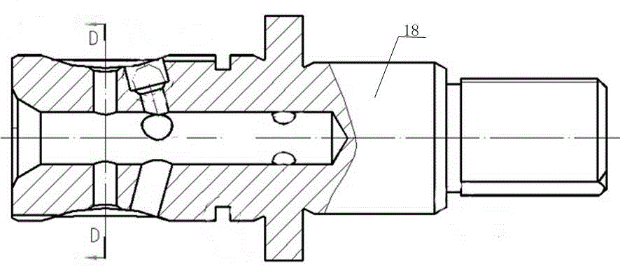
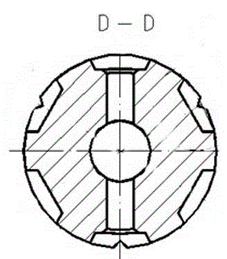
[0002] For such as figure 2 , 3 The input shaft 18 for the steering machine, the spline of the input shaft has six evenly distributed spline grooves in the actual processing process, and there is a depression in the middle of the spline groove, and the processing depth of the depression exceeds 25mm , but at present, the universal milling machine is used to mill large thickness (15mm-25mm) symmetrical grooves. The disadvantages are: low efficiency and poor precision. After processing one groove, it needs to be retracted and turned over to process the symmetrical groove on the other side, resulting in long processing time; Face milling parts are unevenly stressed, resulting in the inability to use large feed rates; low degree of automation

Method used


Image

  • Numerical control opposite-direction slot milling machine
  • Numerical control opposite-direction slot milling machine
  • Numerical control opposite-direction slot milling machine

Examples


Embodiment Construction

[0018] The invention as figure 1 shown.

[0019] Numerical control opposite slot milling machine, including machine tool base 1, the middle part of machine tool base 1 is provided with numerical control work platform 2, the clamp body 3 is provided on the numerical control work platform 2, the two sides of numerical control work platform 2 are respectively symmetrically provided with left and right numerical control sliders Tables 4, 5, left and right CNC sliding tables 4, 5 are respectively provided with left and right machine bodies 6, 7, and left and right milling heads 8, 8 are respectively arranged on the vertical guide rails of left and right machine bodies 6, 7 9, left and right milling heads 8,9 are connecting left and right drive motors 10,11 respectively.

[0020] Left and right machine bodies 6,7 and left and right milling heads 8,9 are locked by left and right locking devices 14,15 respectively.

[0021] Left and right lifting devices 12 and 13 are respectively ...


PUM


Abstract

The invention provides a numerical control opposite-direction slot milling machine which comprises a machine tool base, wherein a numerical control working platform is arranged in the middle of the machine tool base; the numerical control working platform is provided with a fixture body; a left numerical control sliding table and a right numerical control sliding table are respectively and symmetrically arranged on the two sides of the numerical control working platform; the left numerical control sliding table and the right numerical control sliding table are provided with a left machine tool body and a right machine tool body, respectively; vertical guide rails of the left machine tool body and the right machine tool body are respectively provided with a left milling head and a right milling head which are connected with a left driving motor and a right driving motor, respectively. The numerical control opposite-direction slot milling machine adopts symmetrical two-way numerical control for simultaneous feed cutting, and solves the three technical problems that machining time is long caused by the factor that a symmetrical slot in the other side can be machined only by retracting and overturning a tool after one slot is machined, large feed amount is not available caused by uneven stress of parts due to single-sided milling, and the degree of automation is low when a large-thickness symmetric slot is milled by a universal milling machine.

Description

technical field [0001] The invention relates to a numerically controlled machine tool, in particular to a numerically controlled facing slot milling machine. Background technique [0002] For such as figure 2 , 3 The input shaft 18 for the steering machine, the spline of the input shaft has six evenly distributed spline grooves in the actual processing process, and there is a depression in the middle of the spline groove, and the processing depth of the depression exceeds 25mm , but at present, the universal milling machine is used to mill large thickness (15mm-25mm) symmetrical grooves. The disadvantages are: low efficiency and poor precision. After processing one groove, it needs to be retracted and turned over to process the symmetrical groove on the other side, resulting in long processing time; Face milling parts are unevenly stressed, which makes it impossible to use large feed rates; the degree of automation is low. Contents of the invention [0003] In order to ...

Claims


Application Information

Patent Timeline
IPC IPC(8): B23C3/30B23C9/00B23Q1/26B23Q1/25
Inventor 肖先红王永红张青
Owner DONGFENG MOTOR PARTS & COMPONENTS GROUP
Learn More