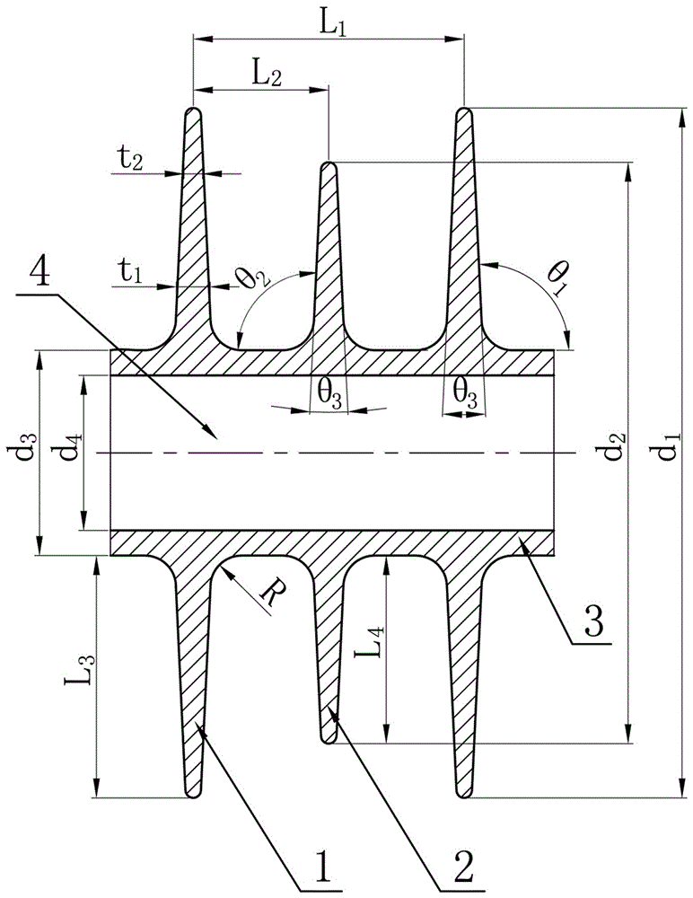
A Composite Insulator Umbrella Structure
A technology of composite insulators and umbrellas, which is applied in the field of external insulation technology and equipment for ultra-high voltage overhead transmission lines, can solve the problems of less research on the umbrellas of tensile composite insulators, and achieve improved pollution flashover resistance, self-cleaning capabilities, and optimized electrical effect
- Summary
- Abstract
- Description
- Claims
- Application Information
AI Technical Summary
Problems solved by technology
Method used
Image
Examples
Embodiment 1
[0018] like figure 1 As shown, a composite insulator umbrella structure described in the embodiment of the present invention includes a mandrel 4, a sheath 3, several large sheds 1 with equal diameters and several small sheds 2 with equal diameters. The large sheds 1 and 2 small umbrella skirts arranged alternately, sheath diameter d 3 is 53 mm, mandrel diameter d 4 is 40mm, the sheath thickness is 6.5mm, and the diameter of the shed is d 1 178mm, small shed diameter d 2 150 mm, umbrella spacing L 1 70mm, minimum umbrella spacing L 2 35 mm, the umbrella of the large umbrella skirt protrudes L 3 62.5mm, the umbrella of the small umbrella skirt protrudes L 4 is 48.5mm, the inclination angle θ of the upper umbrella 1 and the inclination angle θ of the umbrella 2 Both are 92.7°, and the chamfering radius R of the umbrella root is 8mm; the included angle θ between the large shed 1 and the small shed 2 3 Both are 5.3°, and the thickness of the root of the large shed 1 is t ...
Embodiment 2
[0024] The difference between this embodiment and embodiment 1 is the sheath diameter d 3 45.06mm, mandrel diameter d 4 is 34.86mm, then the thickness of the sheath is 5.1mm, and the diameter of the large shed is d 1 is 151.3 mm, and the diameter of the small shed is d 2 127.5 mm, umbrella spacing L 1 59.5mm, minimum umbrella spacing L 2 29.75 mm, the umbrella of the large umbrella skirt protrudes L 3 53.12mm, the umbrella of the small umbrella skirt protrudes L 4 is 41.22mm, the inclination angle θ of the upper umbrella 1 and the inclination angle θ of the umbrella 2 Both are 78.8°, and the chamfering radius R of the umbrella root is 6.8mm. The angle θ between the big shed 1 and the small shed 2 3 Both are 4.5°, and the thickness t of the shed root of the large shed 1 1 is 7.41 mm, and the thickness of the shed edge of the large shed 1 is t 2 is 4.04mm.
Embodiment 3
[0026] The difference between this embodiment and embodiment 1 is the sheath diameter d 3 is 60.94 mm, mandrel diameter d 4 is 47.14mm, the sheath thickness is 6.9mm, and the diameter of the large shed is d 1 is 204.7 mm, and the diameter of the small shed is d 2 172.5 mm, umbrella spacing L 1 80.5mm, minimum umbrella spacing L 240.25 mm, the umbrella of the large umbrella skirt protrudes L 3 71.88mm, the umbrella of the small umbrella skirt protrudes L 4 is 55.78mm, the inclination angle θ of the upper umbrella 1 and the inclination angle θ of the umbrella 2 Both are 106.6°, and the chamfer radius R of the umbrella root is 9.2 mm. The angle θ between the big shed 1 and the small shed 2 3 Both are 6.1°, and the thickness t of the shed root of the large shed 1 1 is 10.03 mm, and the thickness of the shed edge of the large shed 1 is t 2 It is 5.46mm.
PUM
| Property | Measurement | Unit |
|---|---|---|
| diameter | aaaaa | aaaaa |
| diameter | aaaaa | aaaaa |
| thickness | aaaaa | aaaaa |
Abstract
Description
Claims
Application Information
 - R&D
- Intellectual Property
- Life Sciences
- Materials
- Tech Scout
- Unparalleled Data Quality
- Higher Quality Content
- 60% Fewer Hallucinations
Browse by: Latest US Patents, China's latest patents, Technical Efficacy Thesaurus, Application Domain, Technology Topic, Popular Technical Reports.
© 2025 PatSnap. All rights reserved.Legal|Privacy policy|Modern Slavery Act Transparency Statement|Sitemap|About US| Contact US: help@patsnap.com

