
Carbon deposition prevention gasifier

A technology for gasification furnaces and carbon deposition prevention, which is applied to household furnaces/stoves, granular/powdered fuel gasification, and combustion methods. Poor practicability and other problems, to achieve the effect of good carbon removal effect, high practical value, and stable combustion

Inactive Publication Date: 2014-01-29
江苏建总控股集团有限公司
View PDF8 Cites 0 Cited by
  • Summary
  • Abstract
  • Description
  • Claims
  • Application Information

AI Technical Summary

Problems solved by technology

[0003] The purpose of the present invention is to provide a simple structure and low practicability for solving the problem that the gasification furnace in the prior art is easy to deposit carbon, which affects the combustion efficiency and service life of the gasification furnace, and the carbon deposition removal device in the prior art is complicated in structure and poor in practicability. Stable combustion, good carbon removal effect, anti-carbon deposition gasification furnace

Method used


Image

  • Carbon deposition prevention gasifier
  • Carbon deposition prevention gasifier
  • Carbon deposition prevention gasifier

Examples


Embodiment 1

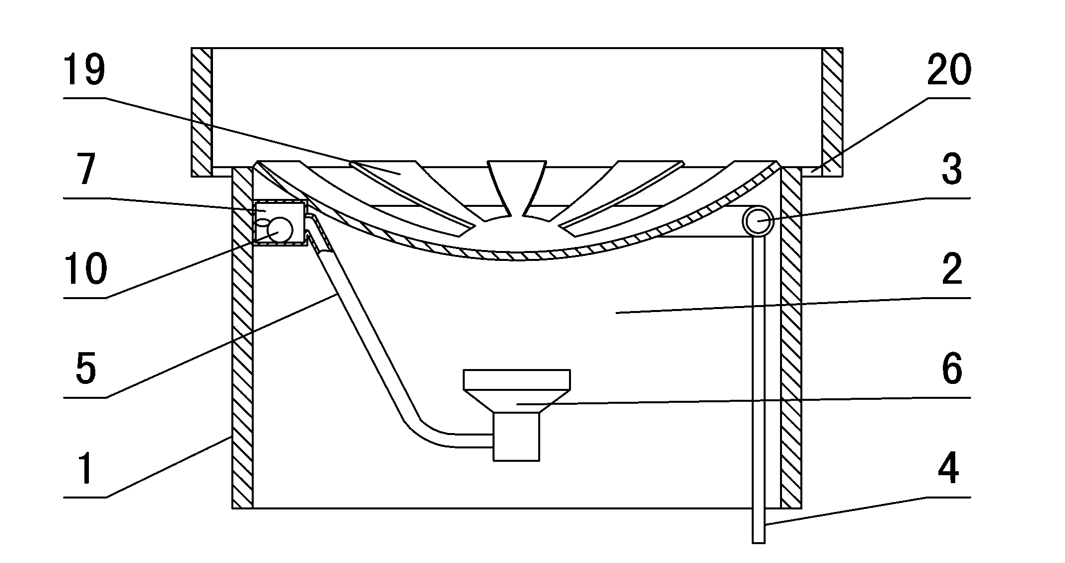
[0027] in such as figure 1In the shown embodiment 1, an anti-carbon deposition gasification furnace includes a fuel delivery pipe 4 and a gasification furnace core. The gasification furnace core includes a furnace core body 1 with a hollow structure. The furnace core wall is provided with annularly distributed ventilation slots 20 between the upper and lower layers of the furnace core wall. The hollow part in the furnace core body is the furnace 2, the top of the furnace is provided with a deflector 19, the position above the furnace close to the inner wall of the furnace core is provided with a circular vaporization tube 3, one end of the vaporization tube is connected to the fuel delivery pipe 4, and the other end is The vaporization nozzle 6 arranged at the lower part of the furnace is connected through the steam outlet pipe 5. The vaporization pipe, the steam outlet pipe and the vaporization nozzle constitute the air flow channel of the gasification furnace. The carbon ch...

Embodiment 2

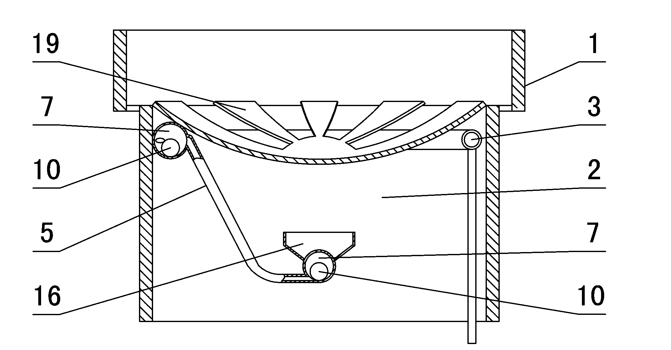
[0029] Its decarbonization cavity of the anti-carbon deposition gasification furnace of embodiment 2 is spherical (see Figure 4 ), set at the connection between the steam outlet pipe and the vaporization nozzle, the carbon removal chamber and the vaporization nozzle are integrally structured, the upper ignition bowl 16 is arranged above the vaporization nozzle, and the gas outlet on the carbon removal chamber is set at the decarbonization nozzle The top of the carbon cavity is where the bottom of the firing bowl is located (see figure 2 ), and the rest are the same as in Example 1.

Embodiment 3

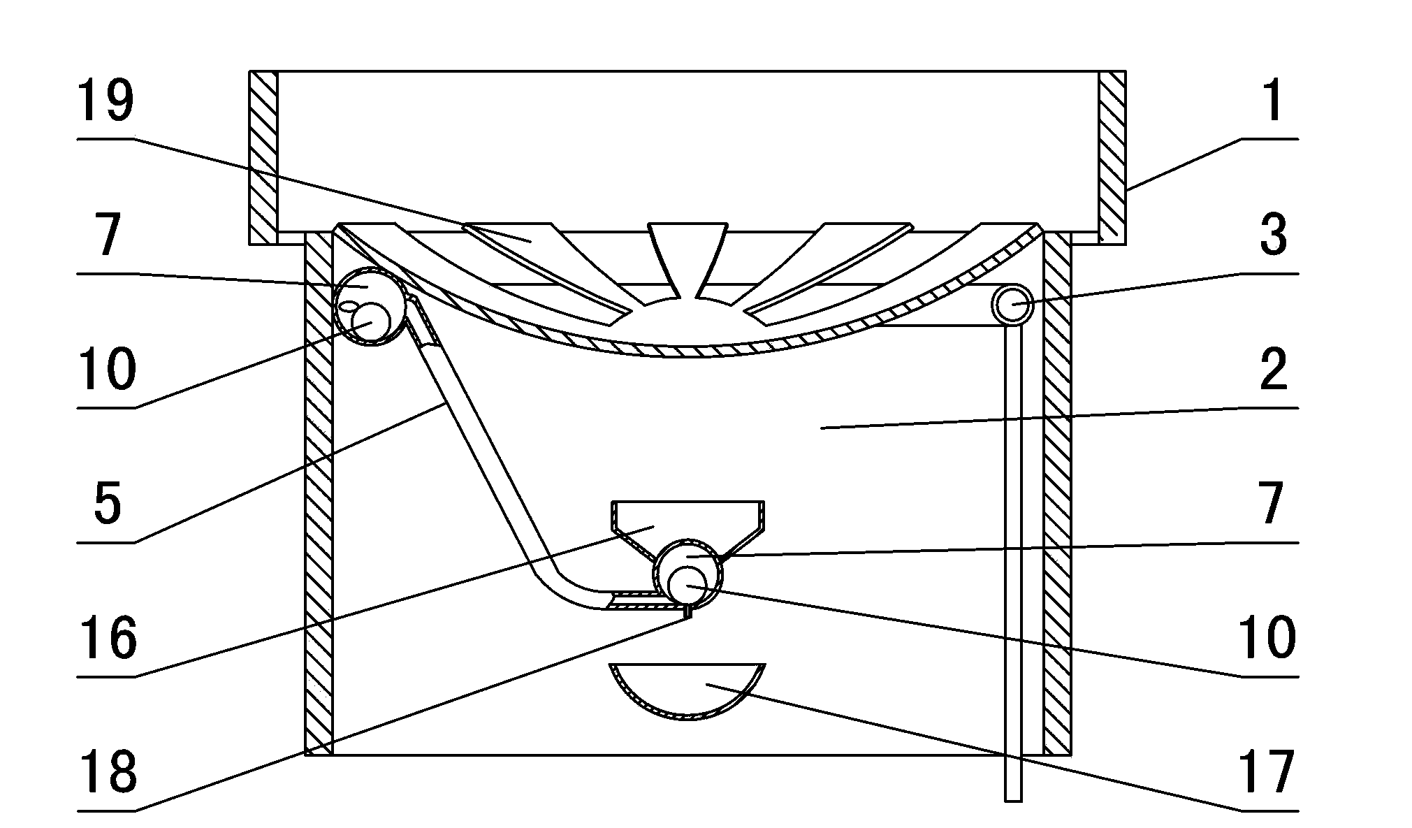
[0031] In the anti-carbon deposition gasification furnace of embodiment 3, the connection between the vaporization pipe and the steam outlet pipe and the connection between the steam outlet pipe and the vaporization nozzle are all equipped with a carbon removal chamber, which is arranged at the connection between the steam outlet pipe and the vaporization nozzle. The bottom is provided with a lower firing bowl 17, and the bottom of the carbon removal chamber at the junction of the steam outlet pipe and the vaporization nozzle is provided with an air leakage port 18 with an opening pointing to the downward firing bowl. The cross-sectional area of ​​the air leakage port is smaller than the gas outlet (see image 3 ), and the rest are the same as in Example 2.


PUM


Abstract

The invention discloses a carbon deposition prevention gasifier. The gasifier comprises a fuel delivery pipe and a gasifier core, wherein a hollow part in the gasifier core is a hearth, an annular gasification pipe is arranged close to the inner wall of the gasifier core above the hearth, the two ends of the gasification pipe are respectively connected with the fuel delivery pipe and a gasification nozzle, the gasification pipe, a gas outlet pipe and the gasification nozzle form a gas flow channel of the gasifier, an expanded decarbonizing cavity is connected to the gas flow channel between the gasification pipe and the gasification nozzle in series, and decarbonizing balls which can freely roll are arranged in the decarbonizing cavity. The gasifier can be utilized for effectively solving the problems that carbon is easily deposited in a gasifier in the prior art, the combustion efficiency and service life of the gasifier are influenced and a deposited carbon removing device in the prior art has a complex structure and poor practicability; the gasifier disclosed by the invention has the advantages of simple structure, good decarbonizing effect, stable combustion and high practical value.

Description

technical field [0001] The invention relates to the technical field of stoves, in particular to an anti-carbon deposition gasification furnace with high combustion efficiency and capable of effectively preventing carbon deposition. Background technique [0002] In existing gasification stoves that use liquid as fuel, the liquid fuel is usually heated and vaporized before being ignited and burned to improve combustion efficiency. The publication date is March 10, 2004, and the Chinese patent document with the publication number CN2606275Y discloses a gasification furnace head, which is composed of an oil inlet, a preheating ring, a pipeline, a cross pipe, a lower nozzle, and an expansion chamber. The mouth is connected with the preheating ring, the preheating ring is connected to the cross pipe through the pipe, and the cross pipe is connected to the lower nozzle downward, and there is an expansion chamber above the lower nozzle. When in use, the fuel is preheated by the preh...

Claims


Application Information

Patent Timeline
Patent Type & Authority Applications(China)
IPC IPC(8): F24C5/02F24C5/12F23D11/02F23D11/44F23D11/36C10J3/34C10J3/52C10J3/72
Inventor 方新成
Owner 江苏建总控股集团有限公司
Learn More