Compressor assembly and compressor with same

A component and outer ring technology, applied in the field of compression, can solve the problems of easy deformation of connecting rods, and achieve the effects of reducing processing difficulty, reducing geometrical tolerance requirements, reducing processing cost and quality control difficulty

Active Publication Date: 2014-01-29
ZHUHAI GREE REFRIGERATION TECH CENT OF ENERGY SAVING & ENVIRONMENTAL PROTECTION
View PDF5 Cites 3 Cited by
  • Summary
  • Abstract
  • Description
  • Claims
  • Application Information

AI Technical Summary

Problems solved by technology

[0007] The purpose of the present invention is to provide a compression assembly, which solves the problem of easy deformation of the connecting rod while reducing its own processing cost and quality control difficulty

Method used


Image

  • Compressor assembly and compressor with same
  • Compressor assembly and compressor with same
  • Compressor assembly and compressor with same

Examples


Embodiment Construction

[0030] The core of the present invention is to provide a compression assembly, which solves the problem of easy deformation of the connecting rod while reducing its own processing cost and quality control difficulty. Another core of the present invention is to provide a compressor with the above-mentioned compression assembly.

[0031] In order to enable those skilled in the art to better understand the technical solutions of the present invention, the present invention will be further described in detail below in conjunction with the accompanying drawings and specific embodiments.

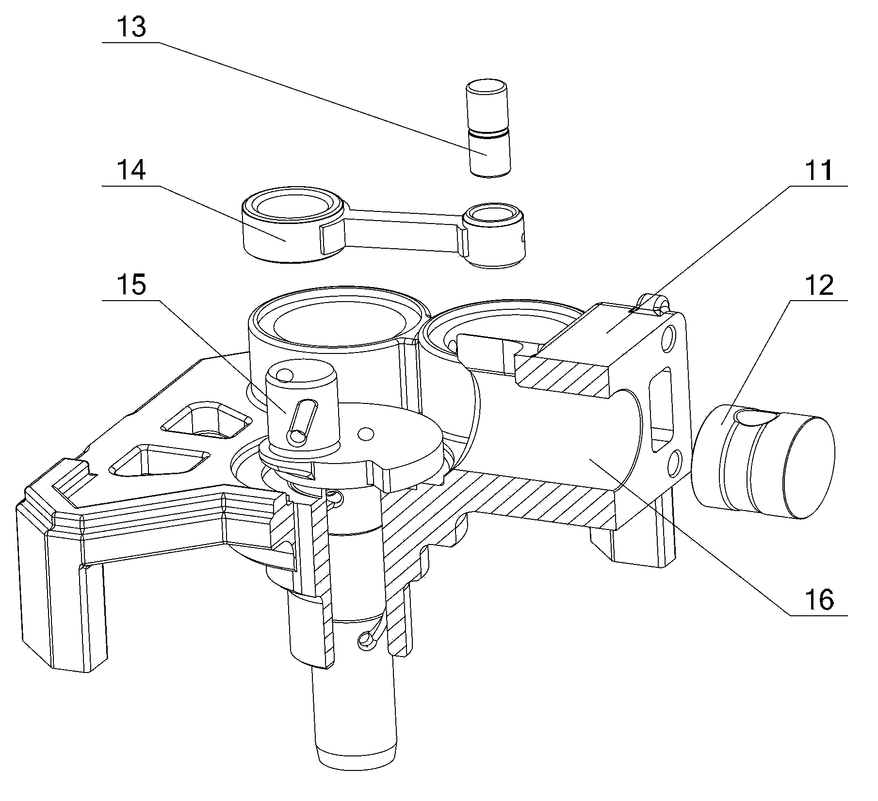
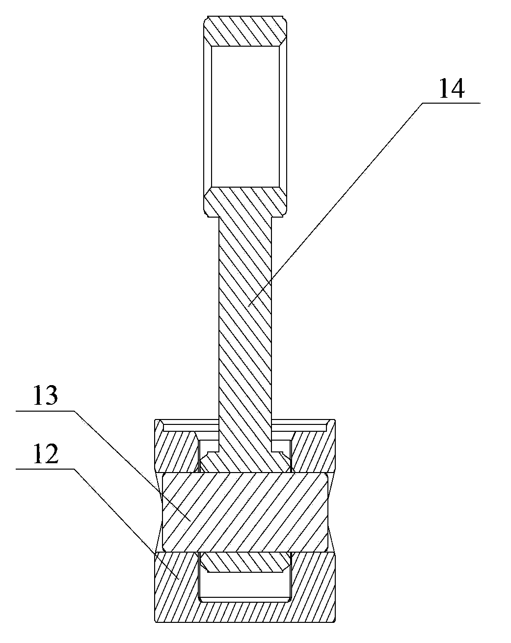
[0032] Such as Figure 4-6 As shown, the compression assembly provided by the embodiment of the present invention includes a connecting rod 34, a piston 32, a crankshaft 35 and a self-aligning connection part. Both the large end and the small end of the connecting rod 34 have cylindrical connecting holes to realize their connection with the piston 32 and the crankshaft 35 , and the piston 32 has ...


PUM


Abstract

The invention discloses a compression assembly. The compression assembly comprises a connecting rod, a piston, a crank shaft and a self-aligning connecting portion. The self-aligning connecting portion comprises an outer ring and a spherical connecting piece, wherein the outer ring is matched with a connecting hole of the end portion of the connecting rod, and the spherical connecting piece is in clearance fit with the outer ring. The self-aligning connecting portion is connected with at least one of the piston and the crank shaft through a through hole formed in the spherical connecting piece. The compression assembly is provided with the self-aligning connecting portion, so that the form and location tolerance requirement of inner parts of the compression assembly is lowered, and therefore the machining cost and the quality control difficulty of the compression assembly are reduced. In addition, due to the fact that the compression assembly enables the end portion of the connecting rod to be still of a connecting hole structure, the problem that the connecting rod is prone to deformation due to arrangement of a sphere head is solved. Besides, the compression assembly further reduces the machining difficulty of the piston, lowers the requirement for materials of the piston and solves the problem that when the inlet portion of the piston is shrunk, the holding force is hard to control. The invention further discloses a compressor with the compression assembly.

Description

technical field [0001] The invention relates to the technical field of compression, in particular to a compression assembly. The invention also relates to a compressor having the compression assembly described above. Background technique [0002] Compression assemblies with pistons, connecting rods and crankshafts as the main components are commonly used components, and are increasingly used in other equipment such as compressors and engines. The structure of the compression assembly in the traditional technology will be introduced below by taking the piston compressor as an example. [0003] Such as figure 1 with figure 2 As shown, in a typical compressor, its compression assembly is arranged inside the body 11, mainly including a piston 12, a connecting rod 14 and a crankshaft 15, the piston 12 is connected to the small end of the connecting rod 14 through a piston pin 13, and the connecting rod The big end of 14 then is sleeved on the eccentric part of crankshaft 15 ...

Claims


Application Information

Patent Timeline
IPC IPC(8): F04B39/00
Inventor 严耀宗崔中赵文钊周宙魏会军
Owner ZHUHAI GREE REFRIGERATION TECH CENT OF ENERGY SAVING & ENVIRONMENTAL PROTECTION
Why Eureka
Try Eureka