Outer wire winding machine for cylindrical workpieces

A wire winding machine and workpiece technology, which is applied in the field of electric pole steel frame manufacturing, can solve the problems of limited inner diameter of the main drum, high manufacturing cost, and influence on production progress, and achieve uniform and reasonable winding spirals, reduce production costs, and save manpower and material resources. Effect

Active Publication Date: 2014-01-29
成都银线电杆有限公司
View PDF7 Cites 6 Cited by
  • Summary
  • Abstract
  • Description
  • Claims
  • Application Information

AI Technical Summary

Problems solved by technology

[0008] 1. Due to the limited inner diameter of the main drum, there is also a pallet trolley to pass through; therefore, it cannot be used for wire winding on the outer surface of cylindrical workpieces such as steel skeletons or rubber tubes with larger diameters.
[0009] 2. The structure of the main drum is complicated, and the relative manufacturing cost is relatively high;
[0010] 3. The steel wire must be wound on the main drum before the wire winding process can be carried out. However, the upper wire is wound on itself after the main drum rotates, and it cannot be produced here. Therefore, the wire feeding is inconvenient, the efficiency is low, and the production progress is also affected.

Method used


Image

  • Outer wire winding machine for cylindrical workpieces
  • Outer wire winding machine for cylindrical workpieces
  • Outer wire winding machine for cylindrical workpieces

Examples


Embodiment Construction

[0057] The specific embodiments of the present invention will be described in detail below in conjunction with the accompanying drawings.

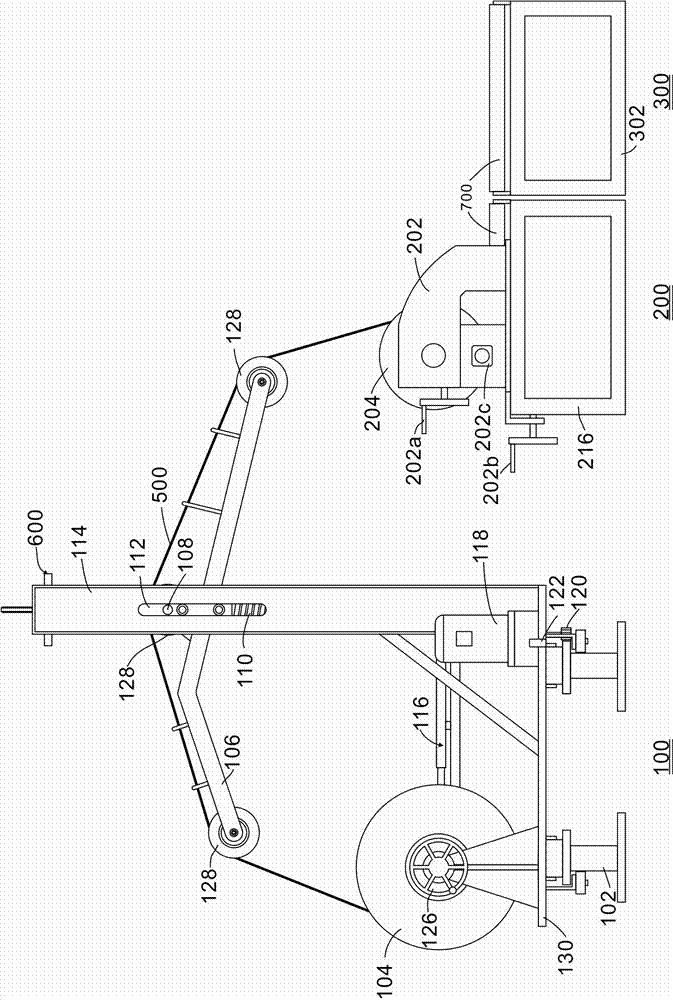
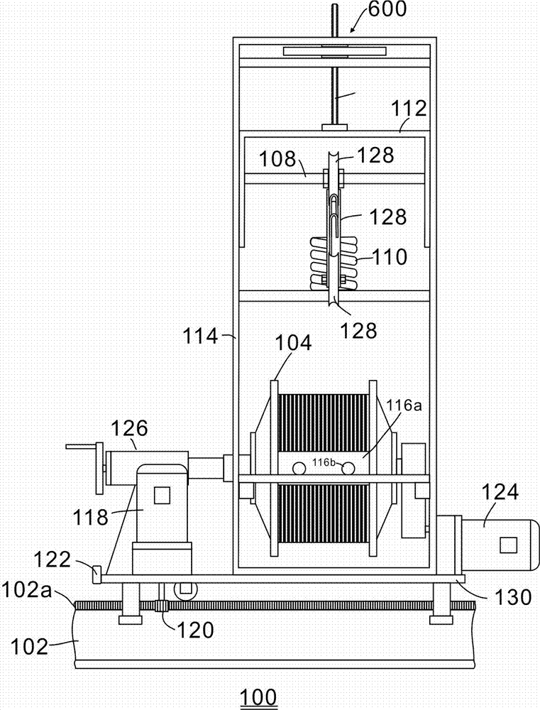
[0058] -Such as Figure 1 to Figure 3As shown, the outer wire winding machine for cylindrical workpieces includes a control system, a wire feeding mechanism 100 and a cylindrical workpiece rotating mechanism 200 arranged aside; The rotating mechanism 200 is responsible for driving the cylindrical workpiece to be wound by the wire to rotate; the two mechanisms cooperate to make the wire 500 tightly and evenly wound on the outer surface of the cylindrical workpiece, without further tightening treatment, which reduces production costs and saves production costs. Time, but also to ensure product quality. For example, when it is used for cold drawing and winding on the outer surface of the steel bar skeleton of the electric pole, since the cold drawing can be tightly wound on the outer surface of the steel bar skeleton of the electric pole, th...


PUM


Abstract

The invention discloses an outer wire winding machine for cylindrical workpieces. The outer wire winding machine comprises a control system, a wire discharge mechanism (100) and a cylindrical workpiece turning mechanism (200); the cylindrical workpiece turning mechanism (200) is arranged on one side of the outer wire winding machine; the wire discharge mechanism (100) comprises a trolley (130) and a wire discharge portion arranged on the trolley (130); the cylindrical workpiece turning mechanism (200) comprises a driving device and a cylindrical workpiece fixing device. The outer wire winding machine has the advantages that the outer wire winding machine can be used for winding wires on the outer surfaces of the cylindrical workpieces with different lengths, different diameters, identical or different top diameters and root diameters or regularly or irregularly changing diameters among top ends and root ends, and the diameters of the cylindrical workpieces are theoretically unconstrained; the cylindrical workpieces can be transferred conveniently after the wires are wound on the outer surfaces of the cylindrical workpieces, so that the work efficiency can be improved; labor and materials can be saved, the work efficiency can be improved, the wires are wound spirally, uniformly, reasonably and tightly without deviation, fastening processing can be omitted, accordingly, the production cost can be reduced, the production time can be saved, and the quality of products can be guaranteed.

Description

technical field [0001] The invention relates to the technical field of steel bar skeleton manufacturing for electric poles, in particular to wire winding equipment therein. Background technique [0002] At present, there are two kinds of steel bar skeletons for electric poles. One is the main steel bar plus a built-in frame force ring welded and formed. At present, it is a traditional mature skeleton that is welded by hand; the second is the main bar plus steel wire spiral rolling. The pole reinforcement skeleton formed outside the main reinforcement is welded with a seam welding machine, which appeared in the mid-1980s and is a relatively new skeleton. [0003] The first type of frame has the advantages of high strength and low cost compared with the second type of frame. [0004] The second type of skeleton is made by hand or machine. [0005] During manual processing, due to limited strength, the steel wire cannot be fastened, and it needs to be bound with thin wire, wh...

Claims


Application Information

Patent Timeline
Patent Type & Authority Applications(China)
IPC IPC(8): B21F3/04B21F23/00
Inventor 周徳志寇西波李长贵
Owner 成都银线电杆有限公司
Why Eureka
Try Eureka