


Quick Research
Generate reliable direction feasibility study reports for your R&D in just a few steps.

Technical Q&A
Discover and master advanced knowledge NOW. Basics, ideas, possibilities, all at once.

Find Solutions
As an expert in R&D theories, this can generate solutions to your technical problems instantly.

Evaluate Feasibility
Analyze your overall solution with one click, know your potential R&D risks in advance.

Monitor Landscape
Get weekly tech updates, stay abreast of the latest tech innovations and key insights.
Power generation switch
A switch and switch board technology, applied in the directions of generators/motors, circuits, electrical components, etc., can solve the problems of large-scale equipment, unsuitability for power generation switches, durability and difficulty in obtaining practical use, etc., to achieve high durability. Effect
- Summary
- Abstract
- Description
- Claims
- Application Information
AI Technical Summary
Problems solved by technology
Method used
Image

Examples
Embodiment approach 1
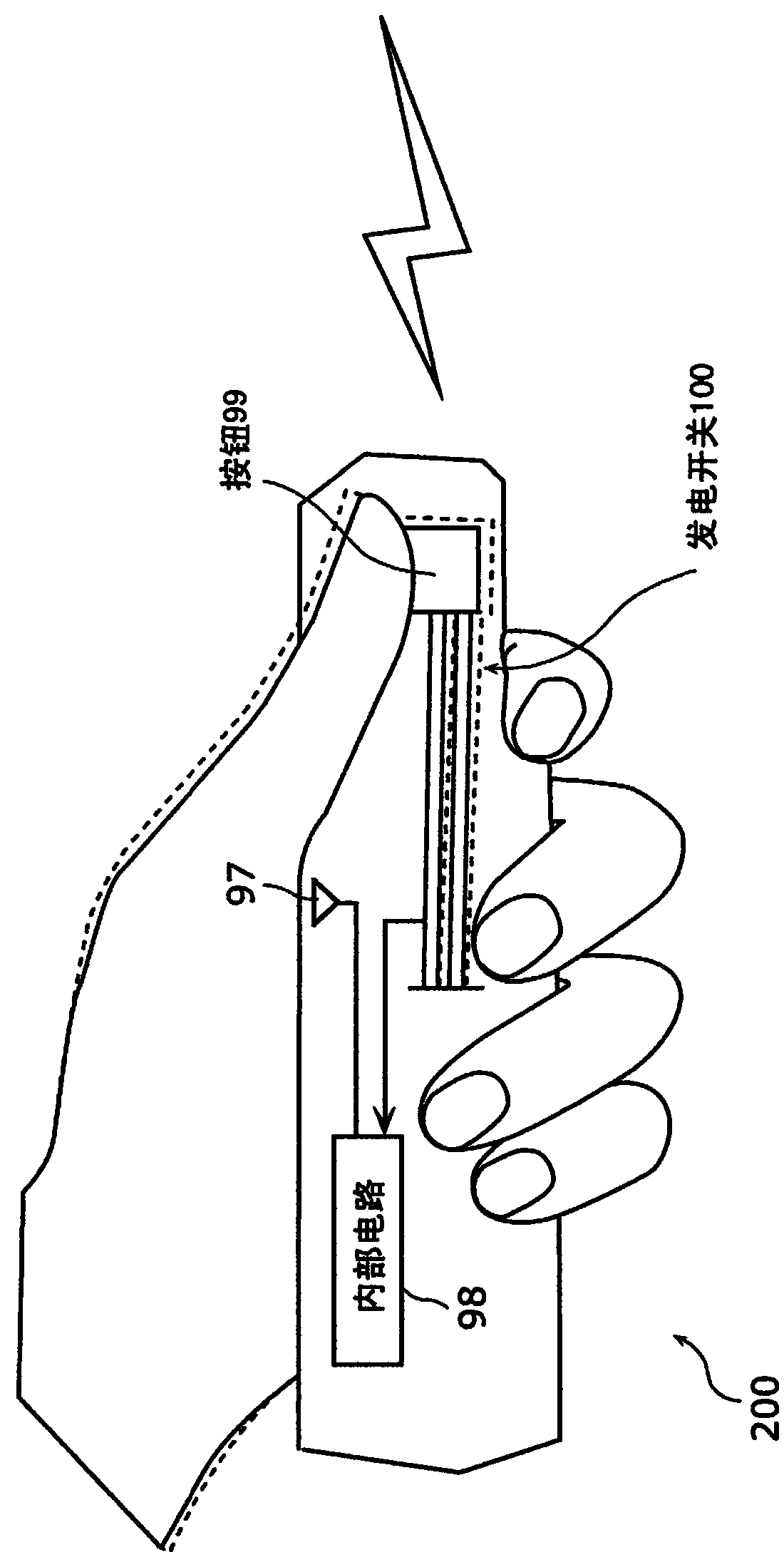
[0094] First, the configuration of the generator switch according to Embodiment 1 of the present invention will be described. figure 1 It is a figure which shows an example of usage of the wireless remote controller 200 provided with the power generation switch concerning Embodiment 1 of this invention. Such as figure 1 As shown, the wireless remote controller 200 includes a button 99 and a power generation switch 100 .
[0095] When the user presses the button 99, the force is transmitted to the power generation switch 100, and the power generation switch 100 generates power.
[0096] The generator switch 100 is a generator switch driven by electric power obtained through an inverse magnetostrictive effect generated by a magnetostrictive element. The internal circuit 98 generates a predetermined wireless signal with the electric power generated by the power generation switch 100 , and wirelessly transmits the generated wireless signal from the transmission unit 97 . In a...
Embodiment approach 2
[0161] In the above, in the first embodiment and its modified example, the power generation switch corresponding to the operation of the user pushing the operation member vertically downward has been described.
[0162] Next, refer to Figure 11A ~ Figure 12C , to describe the power generation switch that responds to the action of the user sliding the operation member in the horizontal direction.
[0163] Figure 11A ~ Figure 11C It is a figure which shows the structure of the power generation switch 100b which concerns on Embodiment 2 of this invention. again, yes and Figure 6A ~ Figure 6C The same constituent elements are assigned the same symbols, and detailed descriptions thereof are omitted.
[0164] refer to Figure 11A The power generation switch 100b includes a power generation element 90b and an operating member 50a.
[0165] The power generating element 90b is a member in which the connecting member 10b included in the power generating element 90 is replaced wi...
Embodiment approach 3
[0175] Next, the configuration of the generator switch that can further increase the rigidity of the parallel beam while suppressing an unavoidable external force applied by the user by the principle of leverage will be described.
[0176] Figure 13A ~ Figure 13C It is a figure which shows the structure of the power generation switch 100d which concerns on Embodiment 3 of this invention.
[0177] Such as Figure 13A As shown, the power generation switch 100d includes a power generation element 90d, a hinge 70, and an operation member 72. As shown in FIG.
[0178] refer to Figure 13B and Figure 13C , the hinge 70 is the fulcrum of the lever, the end of the end of the operation member 72 that is in contact with the power generating element 90d is the action point, and the end of the other end of the operation member 72 to which an external force is applied due to the operation of the user is the force point. Therefore, by making the distance from the fulcrum to the force ...
PUM
 Abstract
Description
Claims
Application Information
 - R&D Engineer
- R&D Manager
- IP Professional
- Industry Leading Data Capabilities
- Powerful AI technology
- Patent DNA Extraction
Browse by: Latest US Patents, China's latest patents, Technical Efficacy Thesaurus, Application Domain, Technology Topic, Popular Technical Reports.
© 2024 PatSnap. All rights reserved.Legal|Privacy policy|Modern Slavery Act Transparency Statement|Sitemap|About US| Contact US: help@patsnap.com