High-speed three-state ADC (Analog To Digital Converter)

A technology of analog signal and digital signal, which is applied in the field of high-speed three-state ADC, and can solve problems such as difficult selection of single-chip microcomputers

Inactive Publication Date: 2014-01-22
北京碳值通环境发展中心(有限合伙)
View PDF6 Cites 3 Cited by
  • Summary
  • Abstract
  • Description
  • Claims
  • Application Information

AI Technical Summary

Problems solved by technology

Using a voltage comparator requires at least two I / O ports of the microcontroller to read data. The switching tube control of the capacitance source itself is a group and requires more I / O ports. This solution is used when multiple outputs The selection of single-chip microcomputer becomes difficult

Method used


Image

  • High-speed three-state ADC (Analog To Digital Converter)
  • High-speed three-state ADC (Analog To Digital Converter)
  • High-speed three-state ADC (Analog To Digital Converter)

Examples


Embodiment 1

[0018] Embodiment 1: Use a high-speed three-state ADC to realize voltage detection within a certain range, and realize the application of a constant current source of a capacitive source.

[0019] The working principle of the constant current source of the capacitance source is to use the current physical formula of the capacitance Calculate the current passing through the capacitor, because the capacitor itself does not consume current, and the lost current is only the leakage current of the capacitor, so its physical principle can be used to control the constant current source. The output DC voltage of the capacitor source is equal to the average value of the ripple voltage at the output ports of the capacitor matrix. In the capacitance source, the interpretation of this formula is: du, dt, and C all refer to the value obtained by the output port of the capacitance matrix, and du refers to the ripple voltage value obtained by the port, that is, du=U max -U min , dt refers...

Embodiment 2

[0026] Embodiment 2: Integrated into a chip with a high-speed three-state ADC model structure

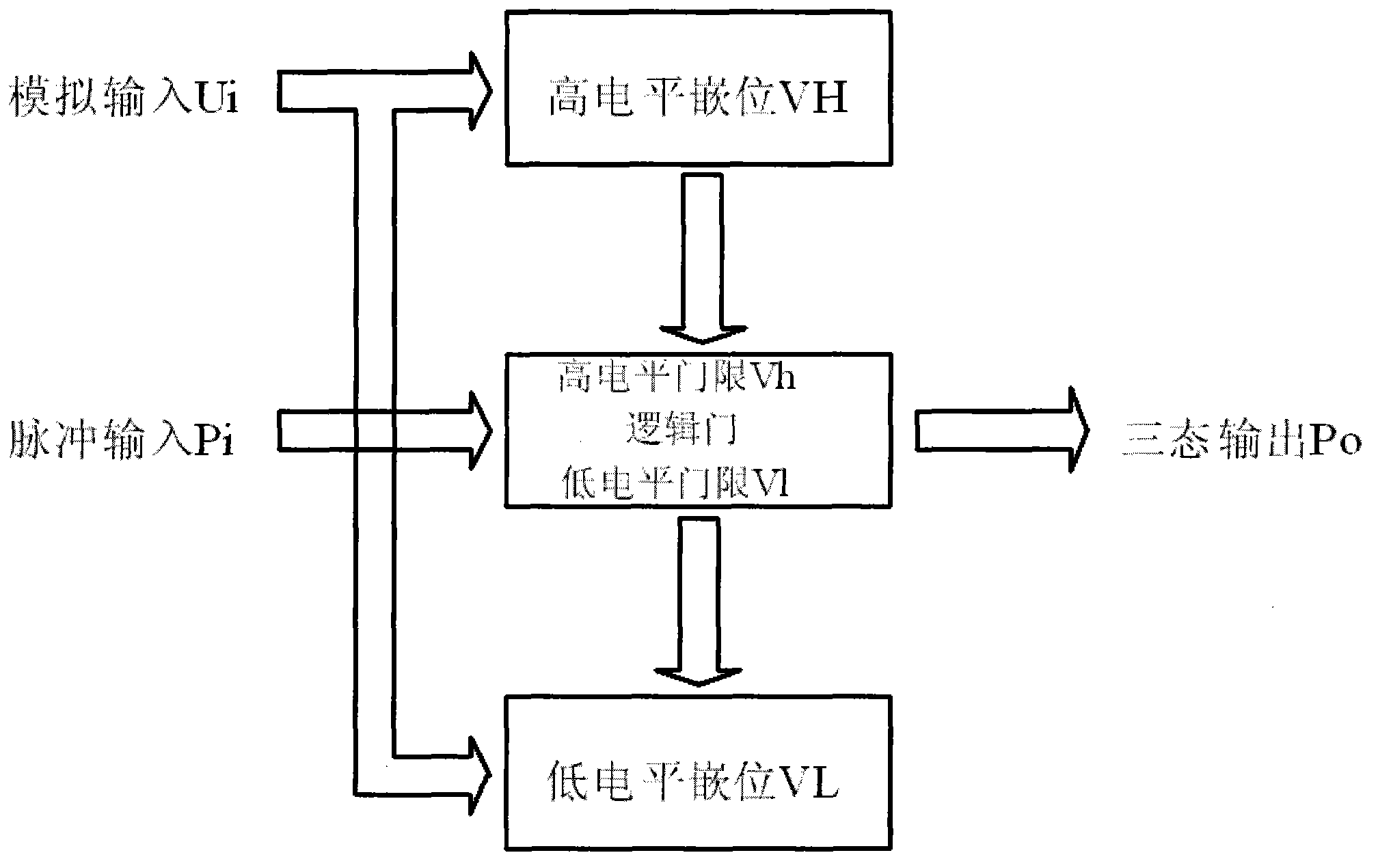
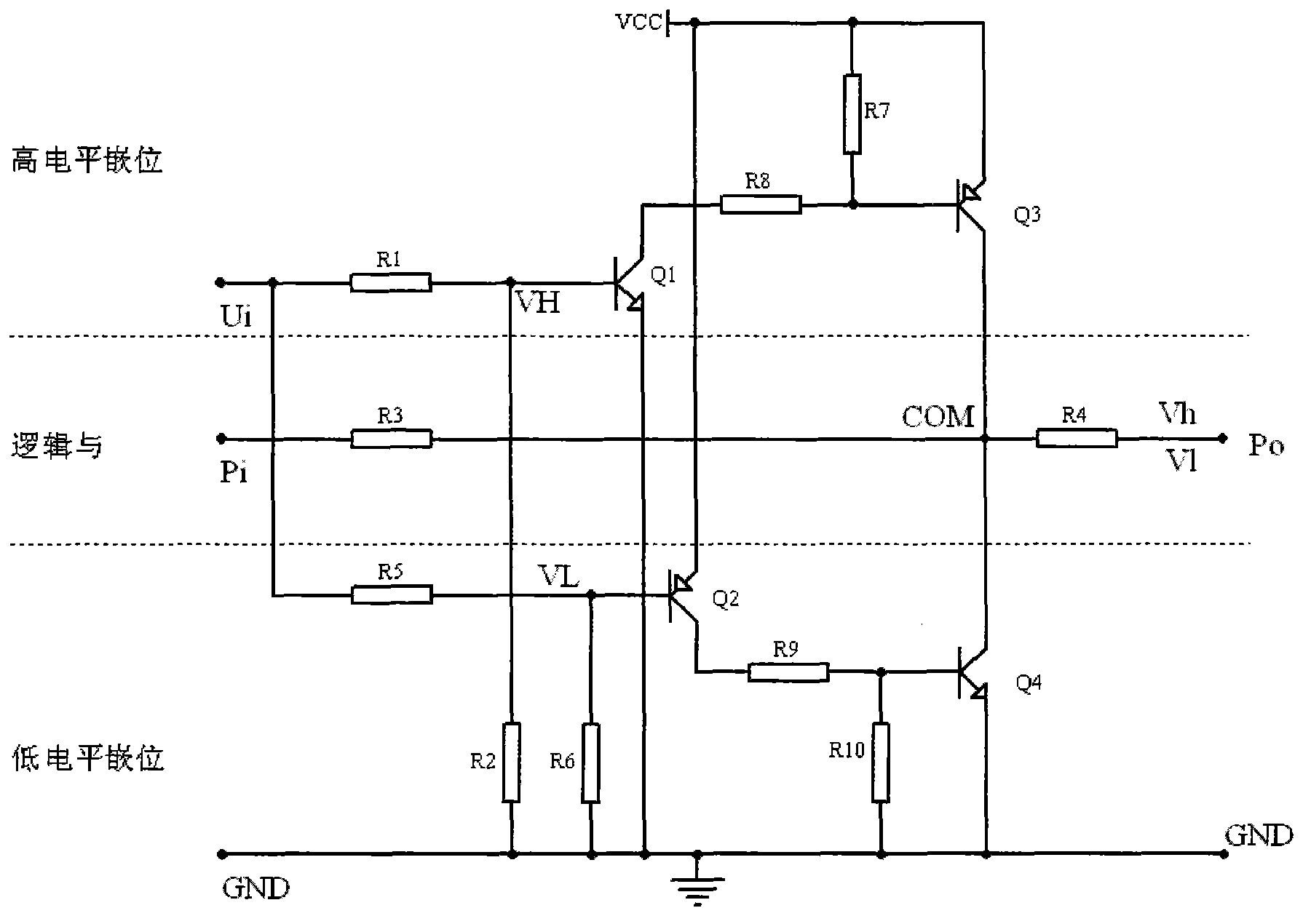
[0027] The function of the ADC chip is that the output data corresponds to the input analog voltage, so it only needs two states: there is output within the preset voltage range, otherwise there is no output.

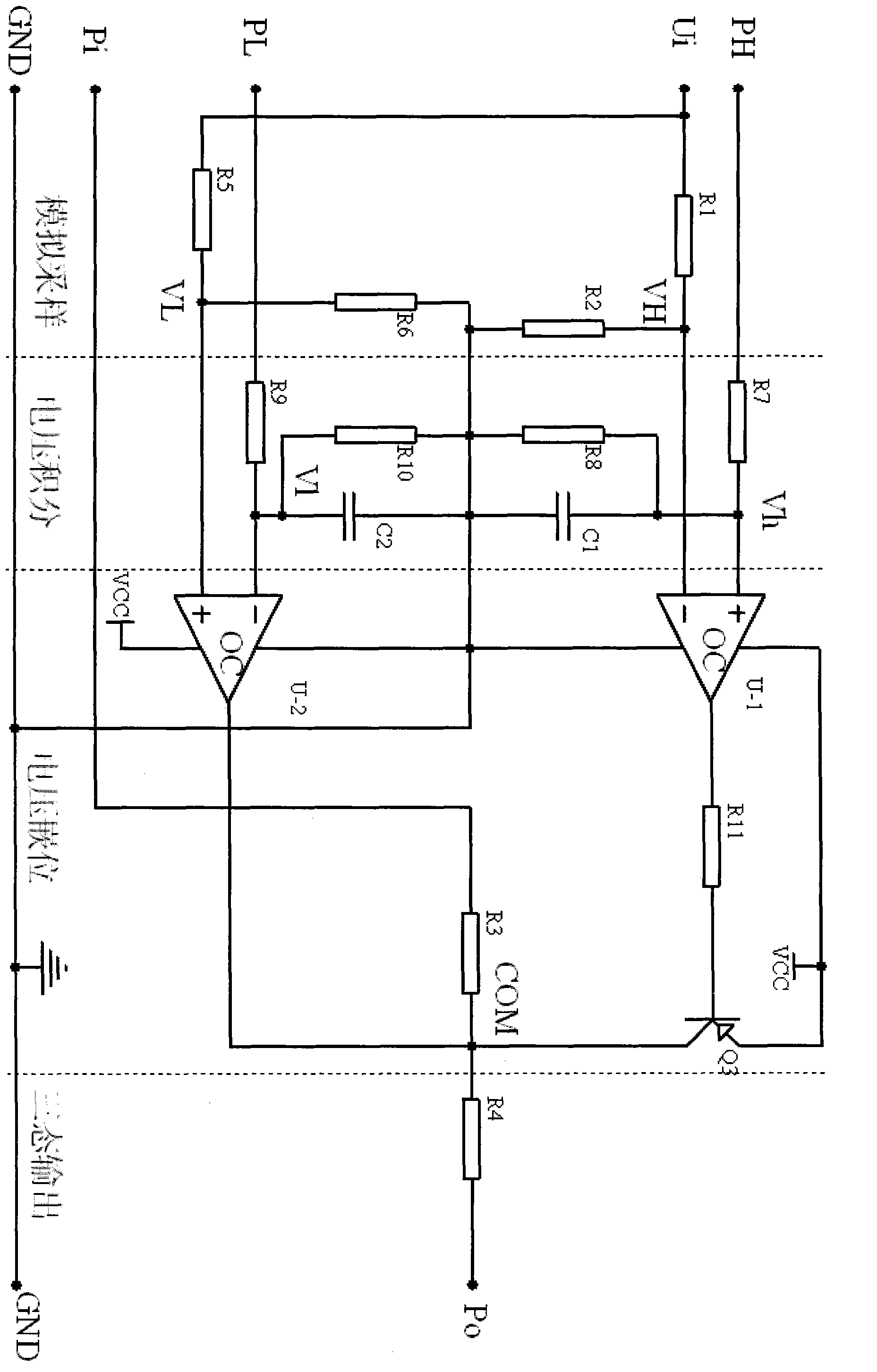
[0028] Circuit structure such as Figure 5 . It is an ADC structure with 8-bit data output, and the conversion accuracy is U i / 256, there are three parts ABC.

[0029] Part A, the input analog signal U i After the current limiting resistor R i into the amplifier, R g is the resistor to prevent the input from floating, C i is the input noise immunity capacitor. The main function of the amplifier is to reduce the current for picking up the analog signal, and at the same time provide sufficient drive current for the clamping circuit, and provide a certain bias voltage for the MOS tube to be directly added to the amplified analog signal. The pulse source here only needs ...


PUM


Abstract

The invention discloses a high-speed three-state ADC (Analog-to-Digital Converter), which belongs to the technical field of analog-to-digital conversion of electronic signals. When a switch of a capacitance source works at a high frequency, high-speed sampling on input and output of the capacitance source is realized, and the output voltage and current quality of the capacitance source is improved. An analog signal Ui is converted into a high-level clamping comparison signal VH and a low-level clamping comparison signal VL according to different proportions respectively, and the voltage value of the VH is higher than that of VL; reference voltages Vh and VI compared with the VH and VL are set in logic and structure respectively; when VH is greater than Vh, Po is equal to 1; when VL is smaller than VI, Po is equal to 0; when VH is smaller than Vh and VL is greater than VI, Po is equal to Pi; input Uih corresponding to the Vh and input Uil corresponding to the VI form a voltage interval of the analog signal. According to the high-speed sampling applied to the constant-voltage output and constant-current output of the capacitance source, a plurality of structures of different voltage intervals are combined to realize high-speed ADC application of continuous voltage signal sampling and the like.

Description

technical field [0001] The high-speed three-state ADC model belongs to the technical field of analog-to-digital conversion of electronic signals. Background technique [0002] In the design and application of capacitance source, regardless of whether the output is in constant voltage mode or constant current mode, it is often wasteful to choose a single-chip microcomputer with ADC function. Generally, single-chip microcomputers with ADC function often have other functions, and these are not used in capacitance sources. function, because only the highest and lowest values ​​of the ripple voltage at the input and output ports of the capacitor matrix need to be known. The output of the capacitance source is equal to the average value of the highest ripple voltage and the lowest ripple voltage in the constant voltage mode, and the output of the capacitance source is equal to the time derivative of the output ripple voltage difference in the constant current mode. It can be seen...

Claims


Application Information

Patent Timeline
Patent Type & Authority Applications(China)
IPC IPC(8): H03M1/12
Inventor 不公告发明人
Owner 北京碳值通环境发展中心(有限合伙)
Why Eureka
Try Eureka