A charging pile
A charging pile and charging module technology, applied in the direction of collectors, electric vehicles, electrical components, etc., can solve the problem of not being able to supply power to the grid
- Summary
- Abstract
- Description
- Claims
- Application Information
AI Technical Summary
Problems solved by technology
Method used
Image
Examples
Embodiment 1
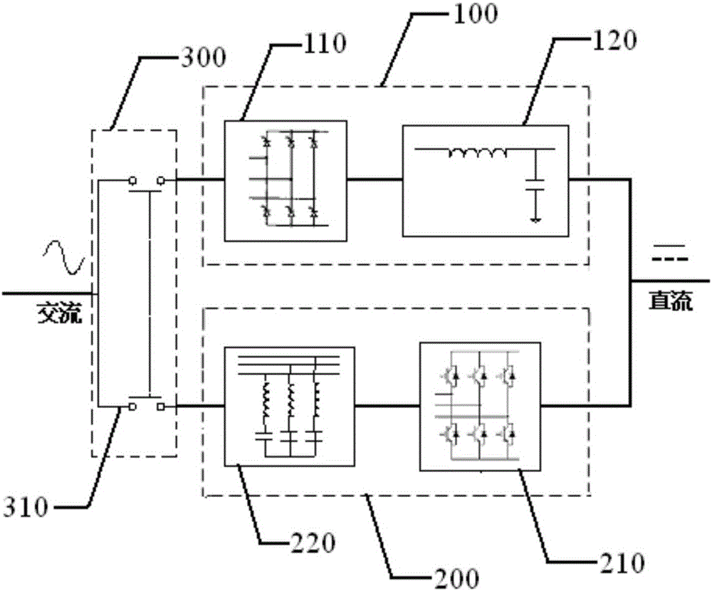
[0034] Embodiment 1 of the present invention discloses a charging pile, please refer to figure 1 , the charging pile includes a charging module 100, a power supply module 200 and a switching module 300, wherein:
[0035] The charging module 100 is used to process the alternating current obtained from the power grid, so as to charge the storage battery.
[0036] Wherein, in this embodiment, the charging module 100 is specifically a rectification circuit, that is, the charging module 100 realizes its function through a rectification circuit, such as figure 1 As shown, the rectification circuit includes a rectifier 110 and a DC filter 120 . The rectifier 110 is used to convert the AC power obtained from the grid into DC power; the DC filter is used to filter the DC power converted from the AC power to obtain filtered DC power for charging the storage battery. After filtering, the DC filter 120 can output the pure direct current required for charging the battery of the electric ...
Embodiment 2
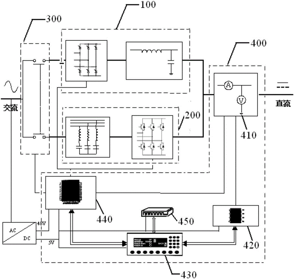
[0045] Embodiment 2 of the present invention discloses another structure of the charging pile, please refer to figure 2 , in addition to the charging module 100 , the power supply module 200 and the switching module 300 of the charging pile in the first embodiment, it also includes an intelligent control module 400 . The intelligent control module 400 includes a meter 410 , a biller 420 , a human-computer interface 430 , a monitor 440 and a communicator 450 .
[0046] The meter 410 is connected with the charging module 100 and the power supply module 200, and is used for recording the charging parameter data when charging the storage battery, and for recording the power supply parameter data when supplying power to the grid.
[0047] Among them, the charging parameter data includes the values of parameters such as current, voltage, battery capacity, and charging power when charging the battery; the power supply parameter data includes the values of parameters such as cu...
Embodiment 3
[0059] Embodiment 3 of the present invention introduces the working process of the charging pile in various charging and power supply modes on the basis of Embodiment 1 and Embodiment 2.
[0060] 1) Fast charging mode
[0061] The electric vehicle battery is connected to the charging handle of the charging pile, and then the monitor monitors that the battery is connected, and displays it through the human-computer interaction device. At this time, the user selects the fast charging mode on the human-computer interaction interface, and the monitor receives the fast charging mode instruction issued by the human-computer interaction device, and responds to the fast charging mode instruction and sends an instruction to the switch to switch to the rectifier circuit , and then send an instruction to control the rectifier rectifier thyristor to charge the battery with pulse current, then control the battery to stop charging for a period of time, and then continue to charge the batter...
PUM
 Abstract
Description
Claims
Application Information
 - Generate Ideas
- Intellectual Property
- Life Sciences
- Materials
- Tech Scout
- Unparalleled Data Quality
- Higher Quality Content
- 60% Fewer Hallucinations
Browse by: Latest US Patents, China's latest patents, Technical Efficacy Thesaurus, Application Domain, Technology Topic, Popular Technical Reports.
© 2025 PatSnap. All rights reserved.Legal|Privacy policy|Modern Slavery Act Transparency Statement|Sitemap|About US| Contact US: help@patsnap.com


