
A wireless channel-based target pose image measurement method

A technology of wireless channel and image measurement, which is applied in the directions of measuring devices, photogrammetry/video metrology, surveying and navigation, etc. It can solve the problem of low image resolution and bit rate, low wireless channel capacity, and high resolution Image can not be transmitted and other problems, to achieve the effect of ensuring accuracy and measurement accuracy

Active Publication Date: 2016-08-17
BEIJING INSTITUTE OF TECHNOLOGYGY +1
View PDF2 Cites 0 Cited by
  • Summary
  • Abstract
  • Description
  • Claims
  • Application Information

AI Technical Summary

Problems solved by technology

However, limited by the capacity of the wireless channel, the image resolution and bit rate transmitted by this system are low, and the target pose cannot be quantitatively measured.
[0005] The National University of Defense Technology has conducted research on the vision-based space target pose measurement method. In the paper "Research on the vision-based space target position and pose measurement method", it is proposed to accurately measure the target pose under the condition of higher image resolution. method, but this method does not consider the problem that high-resolution images cannot be transmitted under low channel capacity
[0006] The typical wireless channel capacity is not higher than 2Mbps. The above methods cannot achieve high-precision image measurement of the target pose under this low channel capacity. Therefore, it is necessary to design the target pose for the low data transmission conditions of this channel capacity. Image measurement method

Method used


Image

  • A wireless channel-based target pose image measurement method
  • A wireless channel-based target pose image measurement method
  • A wireless channel-based target pose image measurement method

Examples


Embodiment Construction

[0030] The present invention will be described in detail below in conjunction with the accompanying drawings and a typical specific implementation manner.

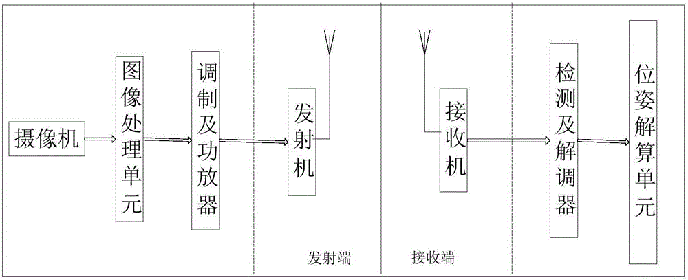
[0031] See attached picture, figure 1 It is a composition block diagram of a system of a target pose image measurement method based on a wireless channel data transmission system in the present invention. The system of the present invention consists of two parts, the transmitting end and the receiving end. Among them, the transmitting end is composed of a camera, an image processing unit, a modulation and power amplifier, and a transmitter; the receiving end is composed of a receiver, a detection and demodulator, and a pose calculation unit. Among them, the transmitting end of the system of the present invention completes functions such as image acquisition, image feature extraction, signal modulation and amplification, and signal transmission; the receiving end completes functions such as signal reception, signal demodul...


PUM


Abstract

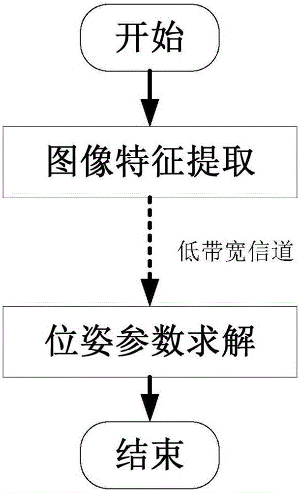
The invention discloses a wireless channel data transmission system based target pose image measuring method, and relates to an image processing and pose measuring technology. The method comprises the following steps: a transmitting end comprising a camera and an image processing unit and a receiving end are arranged, and the image processing unit extracts at least three characteristic points of a shoot image, determines the coordinates of the at least three characteristic points and establishes the matching relationship between the coordinates and a target in prior characteristic to generate image characteristic information data; the image characteristic information data are transmitted to the receiving end from the transmitting end through a wireless channel; and pose parameter resolving is carried out by a pose resolving unit of the receiving end by adopting the received image characteristic information data. The pose image measuring method comprises the steps of characteristic extraction and pose parameter resolving, and satisfies a wireless channel requirement of low capacity by adopting the transmitted image characteristic information data to substitute the whole image. The characteristic extraction is completed under high-resolution and high-frame-rate image conditions, so the pose parameter measuring precision is guaranteed.

Description

technical field [0001] The invention relates to image processing and pose measurement technology, in particular to a target pose image measurement method based on a wireless channel data transmission system. Background technique [0002] Pose image measurement technology has the advantage of not touching the measured object, and has very important application value in scientific research, military, space development and other fields. In some pose measurement scenarios, it is necessary to set observation points on aircraft (such as airplanes, spacecraft, rockets, etc.) to measure the relative pose parameters of flying targets (such as satellites, rockets, etc.) that have relative motion with the aircraft. The observation point set on the aircraft communicates with the ground receiving station through a wireless channel. [0003] The accuracy of image measurement is highly dependent on image resolution and frame rate, and high measurement accuracy can only be obtained when th...

Claims


Application Information

Patent Timeline
Patent Type & Authority Patents(China)
IPC IPC(8): G01C11/00H04N7/18
CPCG01C11/00H04N7/18
Inventor 谌德荣王长元周广铭蒋玉萍高翔霄杨晓乐关咏梅董齐齐赵燕
Owner BEIJING INSTITUTE OF TECHNOLOGYGY
Learn More