A multi-row synthetic tow cooling device
A cooling device and tow technology, used in filament/thread forming, complete sets of equipment for the production of artificial threads, textiles and papermaking, etc., can solve problems such as uniformity defects of filament products, and ensure uniform quality and stability. The effect of sex, structure simplification
- Summary
- Abstract
- Description
- Claims
- Application Information
AI Technical Summary
Problems solved by technology
Method used
Image
Examples
Embodiment 1
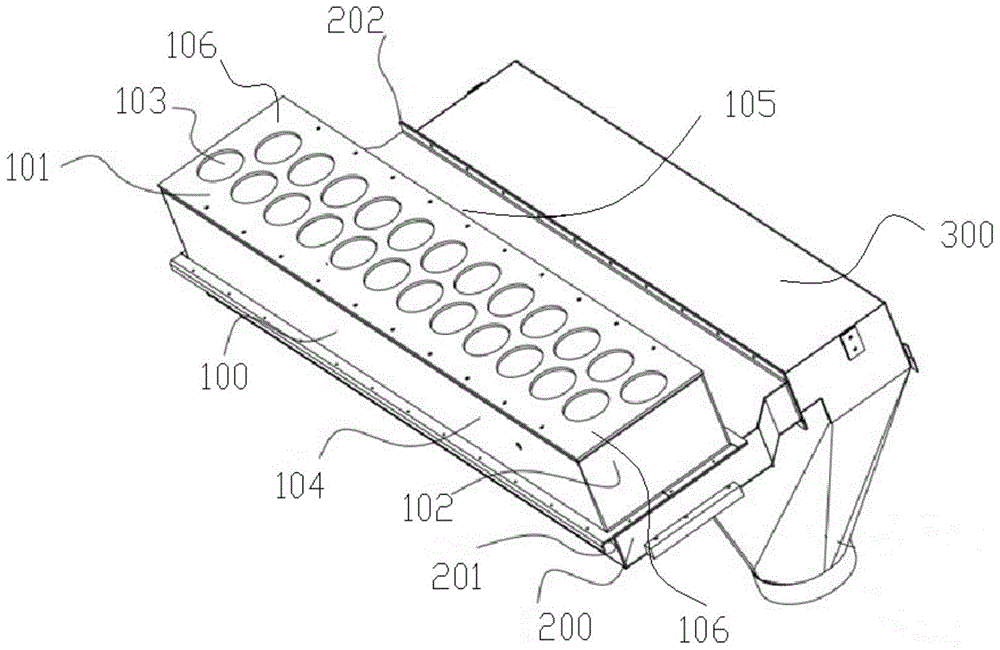
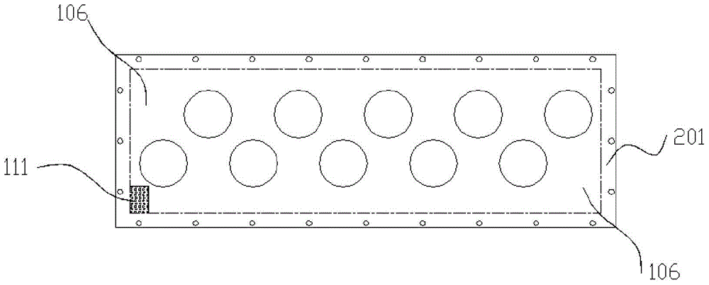
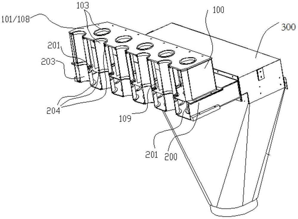
[0054] This embodiment provides a double-row synthetic tow cooling device, such as Figure 3-4 As shown, the double-row synthetic tow cooling device includes a cooling box 100, a housing 200, and a porous plate 201 with a plurality of ventilation holes 111 arranged between the cooling box 100 and the housing 200, wherein the cooling box 100 It includes an upper part 101 and a lower part 102. The upper part 101 includes an upper cover plate 108 and a seal. The lower part 102 is a hollow box structure, and its upper part is connected to the upper part 101 through a seal. After the connection, the The upper part 101 and the lower part 102 are communicated to form a box structure of the cooling box 100 .
[0055] The upper cover plate 108 is provided with two rows of parallel and evenly staggered circular through holes, and the wire mesh cylinders 103 are respectively installed into the interior of the upper part 101 from the position of the above circular through holes, and then en...
Embodiment 2
[0077] The present embodiment provides a double-row synthetic tow cooling device, which is a deformation based on Embodiment 1, such as Figure 9 and Figure 10 As shown, in this embodiment, the wall structure of the cooling box 100 is different from that of Embodiment 1, specifically, the cooling box 100 is a housing, and the housing includes a horizontal inner wall 100c and a horizontal inner wall 100c connected to at least one inclined inner wall 100d, multiple rows of the wire mesh cylinders 103 are respectively arranged parallel to the horizontal inner wall 100c, the adjacent rows of the wire mesh cylinders 103 are arranged in a staggered manner, different rows close to the inclined inner wall 100d A line connecting the centers of a plurality of adjacent wire mesh cylinders 103 forms a straight line, the inclined inner wall 100d is arranged parallel to the straight line, and the inclined inner wall 100d intersects the perforated plate 201 at the hypotenuse 107 . Wherein,...
Embodiment 3
[0080] This embodiment provides a double-row synthetic tow cooling device, which is a modification of Embodiment 1. In this example, if Figure 11 As shown, the means of reducing the amount of cold air entering the first circulation space A through the ventilation holes 111 per unit time is different from that of Embodiment 1. In this embodiment, by changing the perforated plate 201 The arrangement of the ventilation holes 111 is to change the amount of cold air entering the first circulation space A, specifically, the density of the ventilation holes 111 on the perforated plate 201 opposite to the first circulation space A The density of the ventilation holes 111 on the perforated plate 201 opposite to the other circulation spaces B is lower than that of the ventilation holes 111 in the first circulation space A, so that the amount of cold air in the first circulation space A is different from the amount of cool air in the other circulation spaces B. Basically the same.
[...
PUM
 Abstract
Description
Claims
Application Information
 - R&D
- Intellectual Property
- Life Sciences
- Materials
- Tech Scout
- Unparalleled Data Quality
- Higher Quality Content
- 60% Fewer Hallucinations
Browse by: Latest US Patents, China's latest patents, Technical Efficacy Thesaurus, Application Domain, Technology Topic, Popular Technical Reports.
© 2025 PatSnap. All rights reserved.Legal|Privacy policy|Modern Slavery Act Transparency Statement|Sitemap|About US| Contact US: help@patsnap.com


