


Quick Research
Generate reliable direction feasibility study reports for your R&D in just a few steps.

Technical Q&A
Discover and master advanced knowledge NOW. Basics, ideas, possibilities, all at once.

Find Solutions
As an expert in R&D theories, this can generate solutions to your technical problems instantly.

Evaluate Feasibility
Analyze your overall solution with one click, know your potential R&D risks in advance.

Monitor Landscape
Get weekly tech updates, stay abreast of the latest tech innovations and key insights.
An emergency spring for the secondary suspension of locomotives
A secondary suspension and locomotive technology, applied in the field of emergency springs, can solve the problems of no pre-compression function, small rigidity, and affecting vehicle comfort, and achieve the effect of convenient and simple assembly and maintenance operations and simple structure
- Summary
- Abstract
- Description
- Claims
- Application Information
AI Technical Summary
Problems solved by technology
Method used
Image

Examples
Embodiment 1
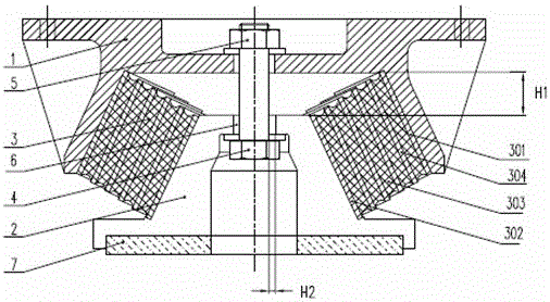
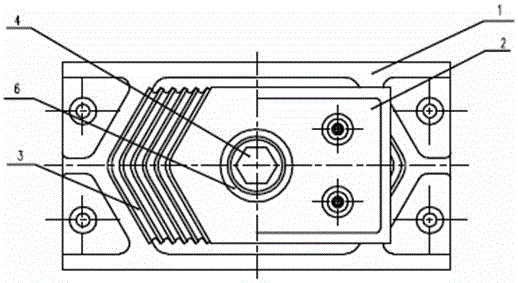
[0023] Such as figure 1 and figure 2 As shown, the emergency spring used for the secondary suspension of the locomotive according to the present invention is mainly composed of an upper cover plate 1, a lower base 2, and a metal rubber damper 3 between the upper cover plate and the lower base. The metal rubber shock absorber is composed of two independent rectangular metal rubber springs, which is a structure in which the upper and lower end plates, the elastic rubber body 303 and the metal partition plate 304 are vulcanized and connected, and arranged in an inverted V shape. The lower side of the upper cover plate is in contact with the upper end plate 301 of the metal rubber spring, and the upper side of the lower base is in contact with the lower end plate 302 of the metal rubber spring. The contact part where the upper and lower end faces of the vibrator are adapted. Such as figure 1 As shown, the lower side of the upper cover plate and the upper side of the lower base...
Embodiment 2
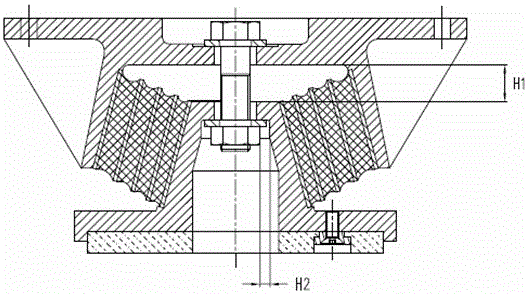
[0029] Such as image 3 and Figure 4 Shown is another embodiment of the present invention, this embodiment is similar to Embodiment 1, the only difference is that the metal rubber vibration damper 3 is an integral type, the shape is similar to the truncated cone top, and the inner hollow cone Shaped, the inner wall and outer surface of the cone are metal rubber spring end plates, which are vulcanized into one with multi-layer elastic rubber bodies and metal partitions. In order to adapt to the conical metal rubber shock absorber, a conical boss is set on the lower base 2, and a conical space that can accommodate the metal rubber spring is set on the lower side of the upper cover plate 1, and the bolt 4 connects the upper cover plate 1, the elastic rubber The shock absorber 3 and the lower base 2 are connected as a whole. In the unloaded state of the emergency spring, the conical upper and lower end surfaces (not the upper and lower end plates) formed by the metal rubber sho...
Embodiment 3
[0031] For the precompression load and stop limit scheme proposed in the technical scheme of the present invention, there is another scheme that can be realized: this embodiment is as follows Figure 5 As shown, the connecting piece that connects the upper cover plate 1, the metal rubber shock absorber 3, and the lower base 2 is a long bolt 4 placed in the horizontal direction. The metal rubber shock absorber is the same as that in Example 1, arranged in a V shape or an inverted V shape; symmetrically on both sides, an oval groove 8 is set on the upper cover plate, and a through hole 6 is set on the lower base (the opposite setting can also be made, That is, the lower base is provided with an elliptical groove and the upper cover is provided with a through hole), and the long bolts pass through the through hole and the elliptical groove to fix the upper cover and the lower base as a whole. Relative to the size, the metal rubber shock absorber is installed between the upper cov...
PUM
 Abstract
Description
Claims
Application Information
 - R&D Engineer
- R&D Manager
- IP Professional
- Industry Leading Data Capabilities
- Powerful AI technology
- Patent DNA Extraction
Browse by: Latest US Patents, China's latest patents, Technical Efficacy Thesaurus, Application Domain, Technology Topic, Popular Technical Reports.
© 2024 PatSnap. All rights reserved.Legal|Privacy policy|Modern Slavery Act Transparency Statement|Sitemap|About US| Contact US: help@patsnap.com